ASME B89.1.10M pdf download
ASME B89.1.10M pdf download DIAL INDICATORS FOR LINEAR MEASUREMENTS
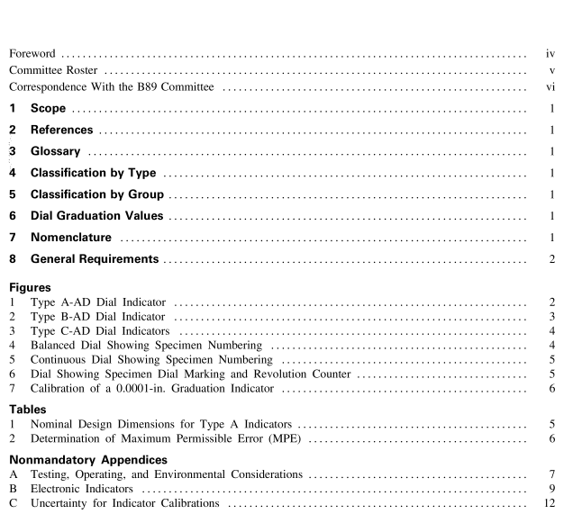
8.2.4 Physical Dimensions. Refer to Fig. 1 for standard dimensions of Type A dial indicators. Types B and C (Figs. 2 and 3) are illustrated for general appearance. The individual manufacturer’s standard practice should be consulted. Table 1 shows size group limits for nominal bezel diameters and corresponding minimum position distances along the spindle axis between contact point and center of dial for Type A indicators.
8.2.5 Dial Faces. The dial faces shall have sharp, distinct graduations and figures. Metric dials shall be yellow. One-revolution dial indicators may have a dead zone at the bottom of the dial face indicating an out- of-range condition. The dead zone may occupy no more than 20% of the circumference of the indicator. There shall be no graduations or numbering within the area occupied by the dead zone. 8.2.6 Dial Markings. Dial markings shall indicate the value of the least graduation, either inch or millime- ter, and shall be in decimals [i.e. 0.001 in., not 1 ⁄ 1000 in.; or 0.01 mm, not 1 ⁄ 100 mm (Fig. 6)].
8.2.7 Dial Numbering. The dial numbering shall always indicate thousandths of an inch or hundredths of a millimeter, regardless of the class of dial marking. 8.3 Repeatability Readings at any point within the range of the indicator shall be reproducible through successive movements of the spindle or lever within ± 1 ⁄ 5 least dial graduation for all types of indicators.
8.3.1 Determination of Repeatability. The fol- lowing procedures are recommended for determining repeatability. (
a) Spindle Retraction. With the indicator mounted normally in a rigid system and its contact point bearing against a nondeforming stop, the spindle or lever is retracted at least five times, an amount approximately equal to 1 ⁄ 2 revolution, and allowed to return gently against the stop. This procedure should be followed at approximately 25%, 50%, and 75% of full range.
(b) Use of Gage Blocks. With the indicator rigidly mounted normal to a flat anvil, position the indicator such that the contact point is slightly lower than the gage block length. Slide a gage block between the contact point and the anvil from four directions: front, rear, left, and right.
(c) The maximum deviation in any of the readings for (a) and (b) above shall not exceed ± 1 ⁄ 5 least dial graduation.
8.4 Accuracy
8.4.1 All types of indicators shall meet the require- ments of Table 2. When determining whether an indica- tor meets the requirements, the measurement uncertainty of the calibration process must be taken into account.
8.4.2 Determination of Error of Indication. The error of indication of a dial indicator is the degree to which the displayed values vary from known displace- ments of the spindle or lever. The determination of error of indication may be done with a micrometer fixture, an electronic gage, gage blocks, an interferometer, or other means. Proper techniques would require that the error of the calibrating means and its resolution be no more than 10% of the least graduation value of the indicator being checked or no more than 25% for indicators having least graduation of 0.0001 in. (0.002 mm) or smaller.
(a) Type A and B indicators are calibrated against a suitable device of known accuracy at a minimum of four equal increments per revolution over the range, starting at approximately the ten o’clock position, after setting the pointer to dial zero at the twelve o’clock position. One revolution indicators shall be started at approximately the seven o’clock position, after setting the pointer to dial zero at the twelve o’clock position.
(b) Type C indicators are calibrated against a suitable device of known accuracy through one revolution of the pointer at a minimum of four equal increments in the clockwise and counterclockwise modes after setting pointer and dial to zero just beyond the pointer rest position.

