ASME B89.1.5-1998 pdf download
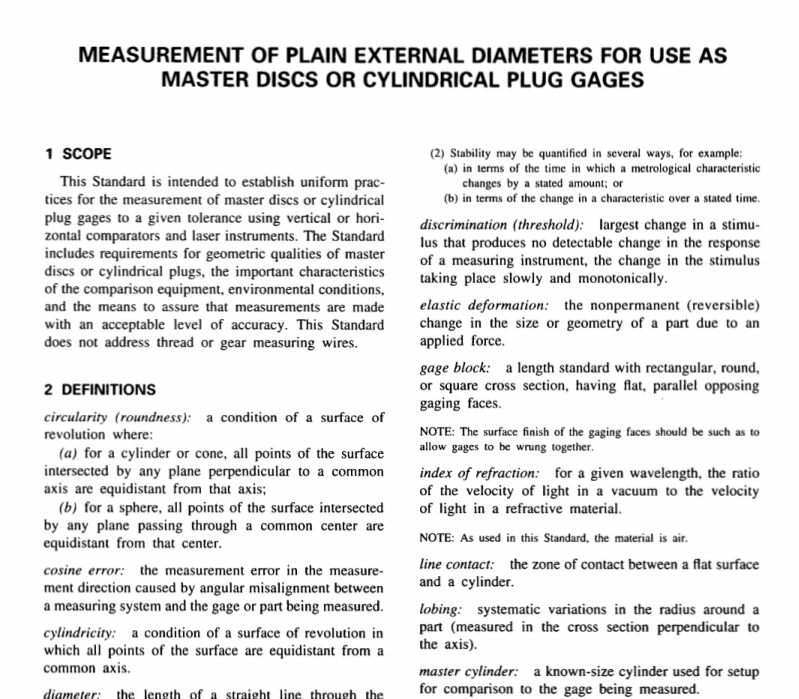
ASME B89.1.5-1998 pdf download MEASUREMENT OF PLAIN EXTERNAL DIAMETERS FOR USE AS MASTER DIscS OR CYLINDRICAL PLUG GAGES
4REQUIREMENTs OF MASTER DIscs AND
cYLINDRICAL PLUG GAGES
4.1 General
The capability of measuring equipment and tech-niques to achieve a high order of precision in thecalibration of master discs or cylindrical plug gages isiimited by relevant features and conditions of the gageto be measured. These are discussed in paras.”4.2through 4.8.
4.2 Design
The design and proportion specifications for gageblanks are given in ASME/ANSI B47.1.
4.3 Material
The material,including coatings or wear inserts,ofmaster discs or cylindrical plug gage blanks shall befree from inclusions or other imperfections that wouldaffect surface texture. The material shall respond toapplicable hardening and stabilizing processes to permitfinishing to the essential surface texture and to assuredimensional stability. Finished surfaces shall have aminimum hardness equivalent to 60 on the RockwellcScale. Master gages shall not be subjected to anyquick aging or shock treatment as a check of stability.
4.4 Surface Texture
The surface texture shall be consistent with the classtolerance of the gage.Table 1 lists maximum roughnessvalues expressed in arithmetic average (R)roughnessvalues. ASME B46.l shall be consulted for referenceinformation.
4.5 Geometric Requirements
4.5.1 General. The diameter will be measured perpara. 6 of this Standard. Typical acceptance criteriafor geometric requirements are diameter measurementsspaced approximately 90 deg apart in each of threeplanes: the midsection,and each end,located 1.6 mm(i6 in.) from inside the ends of corner radii or chamfers.Two-point diameter measurements will not detect theeffect that odd-numbered or irregular lobing has onsize. Diameter measurements taken at multiple locationsmay not fully delect ovality, even-numbered lobing. orstraightness deviation.
lf the gage is measured with nonstandard techniques,such as multiple-point methods or unusually wide planeanvils,the values in Table 3 may not be appropriate.
The purchaser and the manufacturer should consult onacceptable limits in these cases.
The practical application of Table 3 would be tocompare the measured size of a gage to the prescribedsize plus (for Go) or minus (for NOGO) the tabulatedtolerance (for bilateral gages.plus and minus one-halfthe tabulated tolerance). The measured size should fallwithin the size range thus specified. The practicalapplication of Table 2 would be to compare all themeasurements taken on a gage and find the differencebetween the largest and smallest measurements. Thedifference should not exceed the tabulated value.
NOTE:ASME Y14.5M RULE#i(para.2.7.1) DOES NOT APPLYDUE TO THE LIMITATIONS OF PRECISION MEASURINGEQUIPMENTAND THE INABILITY To CORRELATE COMPOs-ITE FORM DEVIATIONs wITH ABSOLUTE SIZE.(Perfect format maximum material condition is not required.)
4.5.2 Roundness. Deviations in roundness can bedetermined at three planes (see para. 4.5.1) perpendicularto the axis of the gage,using a chart type precisionspindle instrument. The out-of-round condition shallnot exceed the value shown in Table 2.ANSI B89.3.1shall be consulted for measurement information. Pluggages used other than as diameter masters,such aslimit gages,shall be evaluated by criteria applicableto the intended use.
4.5.3 Straightness and Taper. Deviations fromsurface element straightness can be determined bymaking axial tracings approximately 90 deg apart usinga profile type instrument. The determined value shallnot exceed the tolerances listed in Table 2. Taper ismeasured as the gradual increase or decrease in diameterover the full length of the gage.
4.6 Face Perpendicularity of Master DiscsThe faces of master discs are not required to beground square to the gaging surface. However.propermeasurement techniques must be followed (see para.6).
4.7 Face Perpendicularity of Plug Gages
Plug gage ends are not required to be perpendicular(square) or controlled. Remove sharp edges to preventdamage to the product being measured and to provide.for the user’s safety. If depth steps are required,endsshall be ground. See Appendix c.
4.8 Tolerance Classes
Master discs and cylindrical plug gages are gradedinto classes identified by xxx.xx.x.Y.Z,and Zz
which determine the total applicable tolerance for a given size. Master discs are to have the total tolerance applied bilaterally (i.e., nominal size with one-half the tolerance applied plus and one-half the tolerance applied minus). Unless otherwise specified, cylindrical plug gages are to have the tolerance all plus on the GO gage and all minus on the NOGO. Gages marked with class identification shall conform to these tolerances, as well as to the other requirements in para. 4.5. Table 3 lists class tolerances.
5 REQUIREMENTS FOR USING REFERENCE GAGE BLOCKS
5.1 Length To achieve optimum accuracy, the calibrated devia- tion of each gage block in the stack shall be summed, then used in the measurement process. Good temperature control becomes increasingly important as the gage diameter increases (see para. 7.4).
