ASME B89.1.2M pdf download
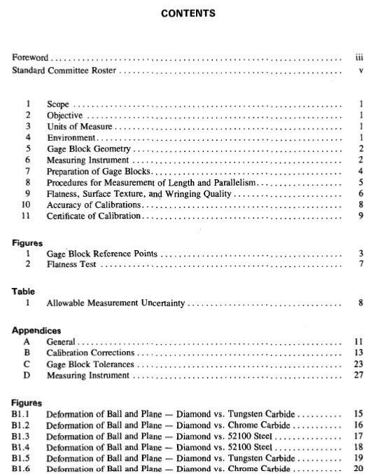
ASME B89.1.2M pdf download Calibration of GageBlocks by ContactComparison Methods(Through 20 in. and 500 mm)
scOPE
This Standard covers procedures to establish unifiedpractice in calibration laboratories for measuring gageblocks up to 20 in. (500 mm) in length (size) by contactcomparison methods. it does not cover interferometriccomparison methods.
2OBJECTIVE
To establish an American standard for laboratory cal-ibration of gage blocks by contact type comparison fortolerance Grade 3 (formerly A and B),Grade 2 (for-merly A +), and Grade 1 (formerly AA), as defined inFederal Specifications GGG-G-15C, and ANSLASMEB89.1.9M,when such calibration is traccablc to NBScalibrated master blocks.
This Standard provides procedures for measuring thelength and parallelism of used gage blocks required forrecalibration and for measuring the length and parallel-ism of new gage blocks requiring certification.
Procedures for determination of flatness,surface tex-ture, and wringing quality are provided , to be used onlyfor new gage blocks or for used gage blocks when spec-ified.
3 UNITs OF MEASURE3.1 Inch Unit of Length
The inch unit of length equals exactly 25.4 millime-ters (mm) in the Metric System.
3.2 Microinch Unit
One microinch equals one millionth (O.000001) of aninch.
3.3 Metric Equivalents
The metric equivalents used parenthetically after inchvalues in this Standard are not necessarily exact conversions, but are the most convenient or rounded off val-ues.
3.4 Micrometer Unit
The metric unit representing one millionth (1/1,0O0,000) of a meter was formerly expressed as one””micron, ” and identified symbolically by the Greek let-ter u (mu). It has been replaced by the name “”microm-eter” and identified by the symbol um. For reasons ofclarity the word “micrometer'” is always spelled out inthis Standard.One microinch equals 0.0254 microme-ter.
4 ENVIRONMENT4.1 Cleanliness
Clcanliness must be maintained in the immediate vi-cinity of the measurement being performed.The criticalsurfaces of the master gage block, the gage block beingcalibrated, and the measuring equipment must be cleanand free of foreign matter and dust particles.
4.2 Temperature
The international standard temperature, at which theactual length of a gage equals its nominal length, is 68RF(20°C).The actual temperature of test gage block,ref-erence gage block,and instrument,must be known ifaccurate and reliable calibrations are to be achieved.The calibration accuracy may suffer when the ambienttemperature departs from standard, by an amount de-pending on the temperature difference and its rate ofchange, the length of the gage blocks, the materials ofwhich they are made,and the accuracy of the coeffi-cients of thermal expansion used in making corrections.Conditions will be improved by thermal shielding ofthe measuring station, the use of a soaking plate,andthe knowledge of the exact temperature of the test blockand reference block as determined by temperature mea-suring devices.
It follows that, in order to achieve the level of accu-racy required for the calibration of gage blocks, the de-viation of the environmental ambient temperature fromthe standard must be held to a minimum. A suggestedmaximum is 土0.5°F(0.25°C) or less. For a completeanalysis of the subject,refer to ANSI B89.6.2-1973,Temperature and Humidity Environment for Dimen-sional Measurement.
4.3 Humidity
Itis recommended that the relative humidity in themeasuring environment shall not exceed 45%.Humid-ity significantly beyond that value may cause problemswith rusting of iron and steel surfaces,and cause per-sonnel discomfort.
4.4 Vibration
Excessive mechanical vibration in the measurementlaboratory may seriously affect the accuracy required forgage block measurement by causing instability at thepoint of mcasurement and at the readout. Vibrationshould be minimized by locating the laboratory awayfrom vibration sources and by using insulating mount-ings for measuring equipment. An ideal solution, usedby some laboratorics, is to support all measuring equip-ment on a massive floating subfloor isolated from thesurrounding structure,the building foundation and thework floor.
5GAGE BLOCK GEOMETRY5.1 Shape
Gage blocks are made in three cross sectional shapes:rectangular, square and round,with and without holes(see Fig.1).
5.2 Reference Points
The reference point is a point located in the plane ofeach gaging surface.The top reference point is locatedfor each shape in relation to the size marking as shownin Fig.1.The bottom reference point is the mirror im-aee of the top reference point.

