IEEE Std 1623 pdf download
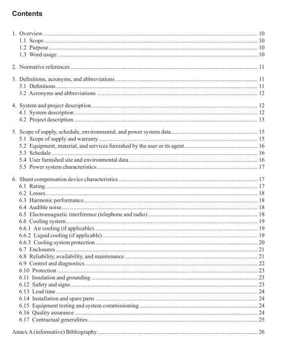
IEEE Std 1623 pdf download IEEE Guide for the Functonal Specifcaton of Medium Voltage (1kV to 35kV) Electronic Shunt Devices for Dynamic Voltage Compensaton
The device can be built with smaller modules connected in parallel or scries.The manufacturer should specifythe module size, the number of modules, the module configuration and the number of modules that can failwithout having to shut down the system.
lf the system contains several modules connected in parallel, equal current sharing among the modules shouldbe achieved by suitable circuits, which are incorporated in the converter modules. The current sharing shouldbe better than 95% among the in-service modules.
lf the system contains several modules connected in series, equal voltage sharing among the modules shouldbe achieved by suitable circuits, which are incorporated in the converter modules. The voltage sharing shouldbe better than 95% among the in-service modules.
6.2 Losses
The supplier should specify the total system losses in idle mode, including transformer losses, in kW and inpercentage of the device rating.In addition, the losses should include all auxiliary loads including cooling fansand pumps, battery chargers, UPS systems,controls, and other auxiliary loads and losses.
Losses evaluation should be performed using____$/kW and.
_S/kWh values.
The supplier should present alternative methods to reduce losses.
6.3 Harmonic performance
Total voltage and current harmonic distortion should be calculated under worst-case system conditions inaccordance with the procedure outlined in IEEE Std 519.These calculations should be done based on thekilovolt ampere capacity and harmonic impedance of the supplying source.
The harmonic distortion should be verified through tests. The test results should be made available to thecustomer.The manufacturer should propose a standardized or industry-accepted test method to verifyharmonic performance.
The device should be configured to avoid resonance with common power system components, including shuntcapacitors.
6.4 Audible noise
Noise generated by the device in idle and full load operation should not exceed_
_dBA and_
dBA respectively.The noise is measured at 3 m from the nearest surface of the device enclosure. The suppliersshould establish existing audible noise level prior to installation of the device. A report should record theaudible noise levels prior to and after the installation of the device. The selection of the noise level shouldcomply with IEEE Std C57.12.90TM
6.5 Electromagnetic interference (telephone and radio)
Radiated and conducted EMIl generated within the device should be suppressed to help prevent excessiveinterference with nearby electronic equipment. The I·T product should be less than ____, where ITis defined as the square root of the sum of the squares of the weighted harmonic current; the correspondingweights are the Telephone Influence Factor(TIF) weighting factors established in 1960(IEEE Std519).
The v·T product should be less than
, where v-T is defined as the square root of the sum of the
squares of the weighted harmonic voltage; the corresponding weights are the TIF weighting factors establishedin 1960 (IEEE Std 519).
The device should not be susceptible to misoperation due to EMI generated by a hand-held general mobileradio service transmitter from a distance of 6.1 cm(2.4 in) in front of the device with the doors closed. Specificfrequencies for testing may be supplied by the user.
Higher frequency electromagnetic emissions can be limited to avoid interference with any properly licensedradio, TV, microwave or other equipment in service. The radio frequency emission produced by the devicemay be less than_
_mVover a range of 0.15 MHz to 1 MHz, when measured 500 m from the building.
The measurement should be made in accordance with IEEE Std 139TM, using a quasi-peak detector reading.
6.6 Cooling system
The cooling system should be able to maintain full capacity at maximum ambient temperature and maximumdevice losses.
The cooling system should be able to operate at the lowest ambient temperature and minimum device losses,and the supplier should describe how this is done.
Replacement of selected critical cooling equipment if defective should be possible while the cooling systemstill operates. However, the user may determine whether this redundancy is required.
The supplier should describe the necessary maintenance actions and their frequency.
6.6.1 Air cooling (if applicable)
Cooling for semiconductors should be by natural convection or forced air.
An air-cooling system should provide full heat rejection with redundancy in blowers, filtering, monitoring.and heat exchangers (if required).
The supplier should describe the air filtering system and details of monitoring of the status of blowers, filters,and other components.
lf filters are used, all air inlets should have exchangeable filters.Filters should be provided with pressuredifferential alarms.
6.6.2 Liquid cooling (if applicable)
A closed loop re-circulating system should provide full heat rejection capacity with redundancy for pumps,heat exchangers, and fans,appropriate to the device availability requirements.
