IEEE C63.12 pdf download
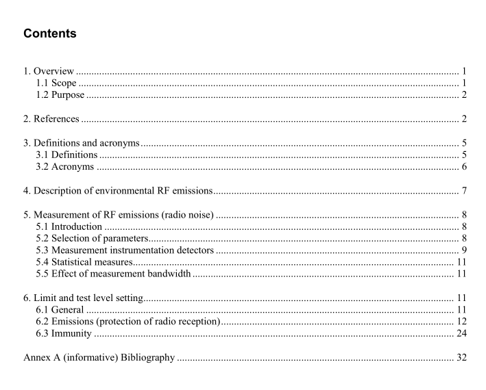
IEEE C63.12 pdf download American National Standard Recommended Practice for Electromagnetic Compatibility Limits and Test Levels
4. Description of environmental RF emissions
The minimum level required for satisfactory receiver reception of desired radiated RF signals is determined in part by the level of environmental RF emissions or undesired signals with which the desired signal must compete with a needed signal-to-noise ratio. If a wanted and unwanted signal are closely spaced in frequency and thus fall into the passband of the receiving device, proper signal reception may not be possible. Several types of RF emissions can influence reception and equipment operation; however, with a particular system and environment, one emission type will generally dominate at a given time, especially if the receiving equipment is located physically near a specific source. Unintentional “receivers” (e.g., information technology equipment) are also subject to interference. Sources of RF emissions usually are divided into two general groups, those emitting broadband and those emitting narrowband noise. The distinction is based on comparison of the emission spectrum with the bandwidth of the measurement instrument used. Broadband noise is frequently impulsive and can be divided further into two groups, natural and man-made. Narrowband noise is usually generated by a variety of restricted radiating devices.
These include industrial, scientific, and medical (ISM) equipment, licensed and unlicensed (e.g., 47 CFR 15) radio transmitters, and digital devices that emit line spectra at harmonics of the clock frequency. Regulated radiating devices generally emit RF energy over a limited portion of the spectrum, clustered around discrete frequencies. Licensed and unlicensed radio transmitters radiate a spectrum near their carrier frequency. The continuing proliferation of low-power portable transmitting sources has increased the need for consideration of the immunity of electronic systems that must operate satisfactorily in close proximity to these sources.
To the extent that RF emissions vary, a time-domain statistical description is necessary. Just how much detail is needed in the description depends upon the nature of the source, the desired accuracy of predicting degradation, and the information bandwidth of the systems with which it might interfere. For many man- made sources, the noise can be characterized as stationary, whereas for natural sources, the noise can occur with variations having time periods ranging from fractions of a second to a year or more.
5. Measurement of RF emissions (radio noise)
5.1 Introduction In determining how to perform measurements of RF emission sources, the following parameters should be kept in mind (see IEEE Std 473-1985):
a) Simple to measure and analyze
b) Such that the interference effect of the noise on the various types of electronic devices or systems likely to be affected can be evaluated
c) Such that they can be related to groups of emitters d) Useful in identifying the source of the measured noise Instrumentation and measurement methods used for determining equipment emission characteristics are described in detail in ANSI C63.2 and ANSI C63.4, respectively. ANSI C63.5 provides techniques for emission measurement antenna calibration. These documents should be reviewed before proceeding to make emissions measurements.
In particular, measurement of RF emissions as described in ANSI C63.4 relates to measurement of emissions from specific devices in a controlled manner at a test facility. This is quite different from measuring ambient noise, as such noise is emitted from many sources, rather than one under test. As might be expected, there is much more control and repeatability in measuring a device than the general RF ambient. To promote repeatability and reproducibility, ANSI C63.4 has specific test setups and procedures and can be used to find the maximum emissions. For conducted emissions, the maximum is found primarily by varying the modes of operation of the device. For radiated emissions, it is much more complex, where a receiving antenna is elevated between 1 m and 4 m to find the point of the in-phase addition of the direct and the indirect reflection as the device is rotated on a turntable. Above 1 GHz, ground plane reflection has little effect. However, in most cases the radiation pattern of devices become more directional. In addition, the antennas used in this frequency range may exhibit directional patterns. Therefore, a height scan and aiming of the receiving antenna are also required to properly measure the maximum emissions of a device under test.
