IEEE C63.16 pdf download
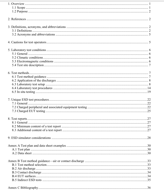
IEEE C63.16 pdf download American National Standard Guide for Electrostatic Discharge Test Methodologies and Acceptance Criteria for Electronic Equipment
5.4.1 General Care should be exercised when selecting a site at which to perform ESD testing. The ESD impulse produces a broad spectral distribution of energy, and these emissions can cause damage or malfunction of unprotected equipment in the immediate area. Also, other equipment in the immediate area can interfere with the ESD test. The ESD test site, therefore, should be located in an area that is of sufficient size so that there is adequate distance from other equipment to reduce the potential for interference. Accordingly, it is recommended that a clear-area radius of at least 0.8 m be provided around the EUT and to any other metallic structure, including walls, so as not to impact the ESD test. Where possible, the EUT should be placed in a dedicated room with electrical isolation from unrelated equipment. The dedicated room can be an environmental room, which is typically a fabricated metal structure that would enable control of temperature and RH levels in the test environment. Because RH levels at the low end of the typical climatic conditions specified in 5.2 are more likely to reveal ESD response or failure, it is recommended that the EUT be evaluated at those lower RH levels. In addition, the low end of the typical RH levels specified in 5.2, or lower as reported from customer sites, might be necessary to evaluate, duplicate, or troubleshoot field issues.
5.4.2 Size of reference ground plane (RGP) An RGP of sufficient size to provide a continuous reference for the EUT, ESD simulator, and operator should be provided as part of the test site. The RGP on the floor should extend beyond the edges of the EUT at least 0.5 m for equipment up to 1 m in height, as well as for a tabletop test. The RGP should be connected to the protective grounding system. Local safety regulations should always be met. See 6.3.2 for information on EUT ground connections. For EUTs that consist of both tabletop and floor-standing equipment, the RGP should extend at least 0.5 m beyond all parts of the EUT.
5.4.3 Insulator materials An insulating support 0.5 mm ± 0.05 mm in thickness, having a relative dielectric constant of 3 to 6, is used to separate the EUT and its associated cabling from metallic surfaces such as the horizontal coupling plane (HCP) for table-top equipment and the RGP for floor-standing equipment. The insulating material should be of sufficient strength to last a reasonable period of time and be resistant to being pierced by a sharp edge of the EUT. In addition, an insulating pallet, 5 cm to 15 cm in thickness, may be placed beneath floor- standing equipment.
6. Test methods
6.1 Test method guidance
6.1.1 ESD simulator The test procedures in this guide are based on the use of an ESD simulator (sometimes called an ESD gun or ESD pistol). The particular simulator used should be appropriate for the EUT, the applicable standard, and the conditions in the EUT’s intended use environment. Simulators are available that represent the hand/metal discharge model and the human/touch discharge model. Simulators representing other relevant ESD discharge models might be available. See Clause 9.
6.1.2 Air or contact ESD methods Air discharges, contact discharges, or both might be appropriate when testing EUTs. The user of this guide should review the advantages and disadvantages of each method, as described in Annex A, prior to selecting which test method to use. However, the general guidance for selecting the discharge method(s) used is as follows:
a) For EUTs with conductive surfaces, the contact discharge method should be used on those surfaces.
b) For EUTs with insulating surfaces, the air discharge method should be used on those surfaces.
c) When performing indirect ESD testing using coupling planes, the contact discharge test method should be used.
6.2 Application of the discharges Discharges should be applied to all selected test points with the EUT operating normally. These test methods may also be applied to EUTs in a nonoperational state (e.g., not connected to an ac power source) to check for destructive responses. Direct contact discharges and air discharges, as well as indirect contact discharges to coupling planes, should be applied where appropriate as determined by the particular EUT and test points selected (see 6.4.3). EUT response can be affected by the polarity of the discharge. Both polarities of discharge (positive and negative) should be used during exploratory testing to determine their effect on the EUT.
6.3 Laboratory test setup
6.3.1 General Tests performed in laboratories are the preferred method for use in following this guide. However, unique in situ tests are acceptable under the limited conditions specified in 6.5.
6.3.2 EUT configuration
6.3.2.1 General The EUT should be configured in a manner representative of the equipment as typically used. A product that is marketed to be operated as a stand-alone device should be tested by itself. Conversely, a product designed and marketed to be operated as part of a multiunit system should be tested in an arrangement with peripherals, accessories, connecting cables, etc., attached and operating in a manner representative of actual use. Configuration of the equipment also includes exercising the equipment in all representative operating modes during the testing process. Multiple samples of the EUT should be available so that if one fails, a substitute EUT can be used to continue the testing. If the EUT needs to be connected to an exerciser during the test, the exerciser should be immune to ESD to facilitate a valid test.
