ASME B1.20.1 pdf download
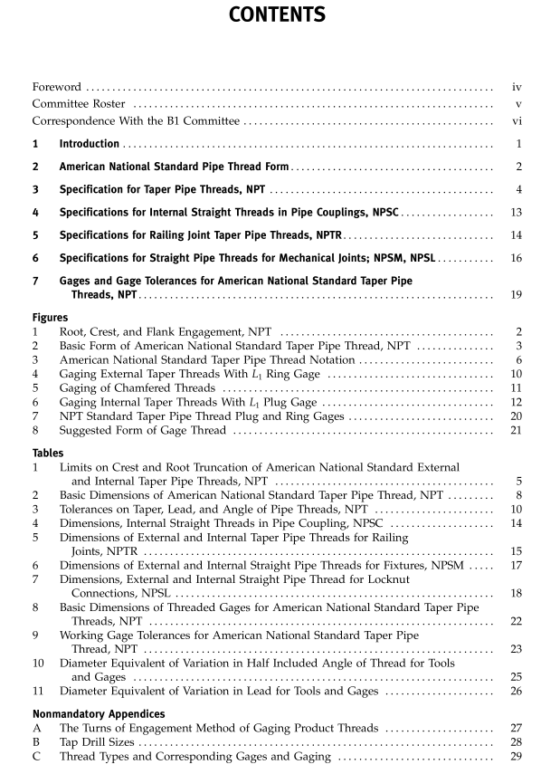
ASME B1.20.1 pdf download Pipe Threads, General Purpose (Inch)
This formula determines the length of effective exter- nal thread. This may include two usable threads incom- plete at the crest.
3.1.8 Hand-Tight Engagement Between External and Internal TaperThreads. The basic length of engagement between external and internal taper threads when screwed together hand-tight is L 1 , shown in column 6, Table 2. 3.1.9 Wrench-Tight Engagement Between External and Internal Taper Threads. The external thread length, L 2 − L 1 , and the internal thread length, L 3 , are allowances for wrench-tight assembly after the hand-tight engage- ment of L 1 lengths.
3.1.9.1 Thread Engagement Considerations. The gagingtolerance of±1 turnfor bothexternaland internal threads has the effect of potentially increasing the length ofengagement by up to two turns or reducing the length of engagement by up to two turns. Working gage wear has the additional effect of reducing thread engagement by the amount gages wear past basic.
3.1.9.2 Special Applications. It is recognized that in special applications, such as flanges for high-pressure work, longer thread engagement is needed, in which case the pitch diameter (dimension E 1 , Table 2) is maintained and the pitch diameter E 0 at the end of the pipe is made smaller. The taper must be kept at 3 ⁄ 4 in./ft, and thread is made longer.
3.1.10 Tolerances on Product Taper, Lead, and Angle. The permissible variations in taper, lead, and angle are given in Table 3. This table is a guide for establishing limits of the thread elements of threading tools. The correct manufacture of tools and the use of gages should provide adequate control of functional size.
3.1.11 Basic Dimensions. The basic dimensions of taper pipe threads, derived from the above specifica- tions, are given in Table 2.
3.2 Gaging NPT Threads The L 1 gages prescribed in this Standard are consid- ered functional in that they give assurance of assembla- bility over the L 1 length, the length of hand-tight engagement. Theysimulatea matingproductthreadthat conforms to this Standard. They encompass multiple elements ofthe thread, includingthread diameters, flank angle, lead, taper, and roottruncation. The simultaneous engagement of all elements results in a measurement that reflects the cumulative variation of all those ele- ments, the functional diameter. This is expressed as standoff for rings and plugs or measured directly by indicating gages. See section 7 for gage specifications.
3.2.1 External Thread Gaging
3.2.1.1 L 1 Ring Gage. The L 1 ring and external product thread are screwed together hand-tight, and the 7 position relative to the small end of the ring (or basic step on a stepped ring gage) is noted (see Figs. 4 and 5). This is the standoff. The tolerance for the standoff is ±1 turn (or ±1 pitch, as shown in column 4 of Table 2) from the small end of the ring (or basic step on a stepped ring).
3.2.1.2 External L 1 -Indicating Gage. The external L 1 -indicating gage is set with a master plug gage, which is made to basic dimensions. Accordingly, when the product is engaged by an indicating gage, readings indi- cate the diametral variation from basic. The tolerance from basic is the diametral equivalent to ±1 pitch (or ±0.0625/n, as shown in column 23 of Table 2).
3.2.2 Internal Thread Gaging
3.2.2.1 L 1 Plug Gage. The L 1 plug gage and inter- nal product thread are screwed together hand-tight, and the position relative to the basic step of the gage is noted (see Figs. 5 and 6). This is the standoff. The tolerance for the standoff is ±1 turn (or ±1 pitch, as shown in column 4 ofTable 2) from the basic step ofthe plug gage.
3.2.2.2 Internal L 1 -Indicating Gage. The internal L 1 -indicating gage is set with a master ring gage, which is made to basic dimensions. Accordingly, when the product is engaged by an indicating gage, readings indicate the diametral variation from basic. The tolerance from basic is the diametral equivalent to ±1 pitch (or ±0.0625/n, as shown in column 23 of Table 2).
3.2.3 Nicked Threads. Pipe threads are particularly susceptible to damage that interferes with proper gag- ing. Generally, this damage appears as “nicks” on the crest of external or internal threads. These nicks will always hold the gage back from properly seating. This makes the external functional size seem larger than it is and the internal functional size seem smaller than it is. Because pipe threads are designed to be installed wrench-tight, and the wrenching reforms the nicks to their proper crest position, some degree of nicking is acceptable. A product mated with a gage may be “rapped” and hand-tightened while engaged. Care should be exercised when rapping to minimize the potential damage to the gage. Rapping and tightening may continue until the product and gage do not engage any further. Products that remain beyond the gaging tolerance after rapping and hand-tightening are nonconforming.

