API TR 522 pdf download
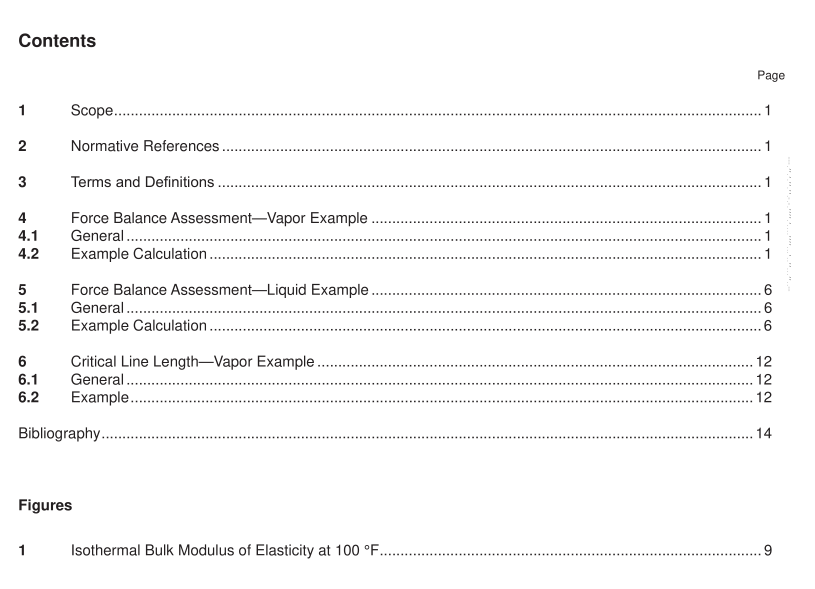
API TR 522 pdf download Technical Report on Pressure-relief System Calculations
This technical report is not a design code. It only provides equations and examples for performing relief systemcalculations. Users are responsible for performing their own calculations and using appropriate referencesfor equations. This report contains a variety of calculation examples for equations and methods found in APIStandard 520, Sizing, Selection, and Installation of Pressure-relieving Devices, Part ll—Installation.
2Normative References
The following referenced documents are indispensable for the application of this document.For dated references,only the edition cited applies. For undated references, the latest edition of the referenced document (includingany amendments) applies.
APl Standard 520, Sizing, Selection, and Installation of Pressure-relieving Devices, Part ll-Installation,7Edition
3Terms and Definitions
3.1
physical acoustic line length
The axial linear distance from the PRV inlet flange to the first significant acoustic reflection point.See APl 520,Part ll,Annex c.
3.2
speed of sound
The distance traveled per unit time by a sound wave as it propagates through an elastic medium.
3.3
spring constant
Acharacteristic of a spring that is the ratio of the force affecting the spring to the displacement caused by it.
4Force Balance Assessment-Vapor Example
4.1General
This is an example of a force balance assessment from APl 520, Part l, Section 7.3.6.d for simple installation invapor service using reference [1] and [4].
4.2Example Calculation
1) Obtain the valve and installation information.- Valve: 11%2-F·2 bellows, vapor certified.— Relief fluid phase at inlet of PRV: Vapor.- Certified orifice area(A,)= 0.3568 in2.
– Certified coefficient of discharge value(K,) = 0.855 unitless.
— Disc backpressure area(A..)= 0.4638 in2.
— Lift (…) = 0.182 in.
– Set pressure(P ,) = 50 psig.- Vessel MAWP = 50 psig.
— Blowdown(PEp)= 7 % of set pressure = 3.5 psi.-Overpressure (Pop)= 10 % of set pressure = 5.0 psi.
— PRV mounted to a 2-in. Schedule 40 [inner diameter (ID) of 2.067 in. and cross-sectional area(A) of
3.354 in] inlet line pipe that is routed directly to a pressure vessel with no bends.PRV is not mounted ona process line.
– Physical inlet pipe length from vessel to equipment (L) = 15ft.- Physical acoustic line length (L.)= 15ft.
— Non-recoverable frictional inlet pressure loss (AP)= 6 % of set pressure = 3.0 psi.- Rated capacity of relief valve (based on hexane and certified values) = 2860 lb/hr.
– The total backpressure (P.,) = 2.0 psig.This example assumes no effects on set pressure fromsuperimposed backpressure, so the built-up backpressure is equal to the total backpressure.The built-upbackpressure is equal to 4 % of the set pressure.
— Total mass of the PRV(Mpgv)= 45 lbm.
NOTE This is a hypothetical relief valve for which the spring constant, mass in motion, and damped opening time wil beestimated.
2)Determine the fluid properties.
At PRV inlet pipe entrance:
— Fluid composition = 100 % n-hexane vapor.— Relief temperature (T) = 300 °F.
— Relief pressure (P) =(50 psig *1.1+14.7)= 69.7 psia.- Vapor density @ 55 psig = 0.8323 lb/ft3.
— Compressibility (Z) = 0.8852.
— lsentropic expansion coefficient(K)= 0.963.
3)Determine the speed of sound in the vapor at the PRV inlet pipe.
Assume that n-hexane behaves as a real gas and ignore the elasticity of the pipe.The speed of sound for a real gas is given by Equation (1):
