API RP 53 pdf download
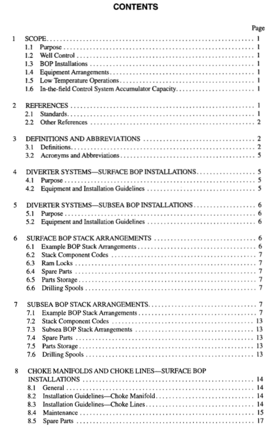
API RP 53 pdf download Recommended Practices for Blowout Prevention Equipment Systems for Drilling Wells
3 Definitions and Abbreviations
3.1 DEFINITIONS The following definitions are provided to help clarify and explain use of certain terms in the context of this publication. Users should recognize that some of these terms can be used in othèr instances where the application or meaning may vary from the specific information provided in this publication.
3.1.1 accumulator: A pressure vessel charged with nitro- gen gas and used to store hydraulic fluid under pressure for operation of blowout preventers (BOPS).
3.1.2 annular preventer: A device that can seal around any object in the wellbore or upon itself. Compression of a reinforced elastomer packing element by hydraulic pressure effects the seal.
3.1.3 articulated line: An articulated line is a choke or kill line assembled as a unit, with rigid pipe, swivel joints, and end connections, designed to accommodate specified rel- ative movement between end terminations.
3.1.4 bell nipple (mud riser, flow nipple): A piece of pipe, with inside diameter equal to or greater than the blow- out preventer bore, connected to the top of the blowout pre- venter or marine riser with a side outlet to direct the drilling fluid returns to the shale shaker or pit. This pipe usually has a second side outlet for the fill-up line connection.
3.1.5 blind rams (blank, master): Rams whose ends are not intended to seal against any drill pipe or casing. The rams seal against each other to effectively close the hole.
3.1.6 blindshear rams: Blind rams with a built-in cut- ting edge that will shear tubulars that may be in the hole, thus allowing the blind rams to seal the hole. Used primarily in subsea BOP systems.
3.1.7 blowout: An uncontrolled flow of well fluids and/or formation fluids from the wellbore or into lower pressured subsurface zones (underground blowout).
3.1.8 blowout preventer (BOP): A device attached to the casinghead that allows the well to be sealed to confine the well fluids in the wellbore.
3.1.9 blowout preventer (BOP) drill: A training pro- cedure to determine that rig crews are familiar with comect operating practices to be followed in the use of blowout prevention equipment. A dry run of blowout preventive action.
3.1.10 blowout preventer (BOP) operating and control system (closing unit): The assembly of pumps, valves, lines, accumulators, and other items necessary to open and close the blowout preventer equipment.
3.1.11 blowout preventer (BOP) stack: The assembly of well control equipment including preventers, spools, valves, and nipples connected to the tp of the casinghead.
3.1.12 blowout preventer (BOP) test tool: A tool to allow pressure testing of the BOP stack and accessory equip- ment by sealing the wellbore immediately below the stack.
3.1.13 buffer tank: A targeted, horizontal, cylindrical tank that changes the direction of fluid flow downstream of the choke and serves as a flow director to the flare line or gas buster.
3.1.14 casingheadspool: The part of the wellhead to which the BOP stack is connected. 3.1.15 choke: A device with either a fixed or variable aperture used to control the rate of flow of liquids and/or gas. 3.1.16 choke line valve: The valve(s) connected to and a part of the BOP stack that controls the flow to the choke manifold.
3.1.17 choke manifold: An assembly of valves, chokes, gauges, and lines used to control the rate of flow from the well when the BOPs are closed.
3.1.18 clamp connection: A pressure sealing device used to join two items without using conventional bolted flange joints. The two items to be sealed are prepared with clamp hubs. These hubs are held together by a clamp contain- ing two to four bolts. 3.1.19 close-assist valve: A valve capable of automati- cally closing via mechanical or hydraulic means, or a combi- nation thereof. 3.1.20 closing ratio: The ratio of the wellhead pressure to the pressure required to close the BOP.
3.1.21 conductor pipe: A relatively short string of large diameter pipe that is set to keep the top of the hole open and provide a means of returning the upflowing drilling fluid from the wellbore to the surface drilling fluid system until the first casing string is set in the well. Conductor pipe is usually cemented.
3.1.22 control manifold: The system of valves and pip- ing to control the flow of hydraulic fluid to operate the vari- ous components of the BOP stack.
3.1.23 control panel, remote: A panel containing a series of controls that will operate the valves on the control manifold from a remote point.
3.1.24 control pod: An assembly of subsea valves and regulators that when activated from the surface will direct hydraulic fluid through special apertures to operate the BOP equipment.
