API Publ 4712 pdf download
API Publ 4712 pdf download Gas-Fired Steam Generator— Test Report Site C Characterization of Fine Particulate Emission Factors and Speciation Profiles from Stationary Petroleum Industry Combustion Sources
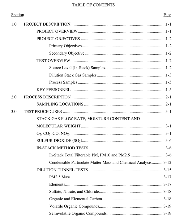
Condensible Particulate Matter Mass and Chemical Analysis CPM was determined using EPA Method 202; total sampling time was six hours for all runs. After the in-stack filter, the sample passed through a heated Teflon line to a series of four impingers placed in the ice bath used for the Method 201A train. The first two were standard Greenburg-Smith impingers containing distilled deionized (DI) water. The others were modified Greenburg-Smith impingers; the third was empty for Runs 1 and 2, and contained DI water for Run 3; the fourth contained silica gel. A quartz filter was placed between the second and third impingers to improve capture efficiency for any aerosols that may have passed the first two impingers. At the conclusion of each run the impingers were purged with nitrogen for one hour in an attempt to eliminate dissolved SO 2 .
The contents of the impingers were recovered with DI water and dichloromethane, as shown in Figure 3-7. Previous tests (England et al., 2000) have found that a majority of the particulate matter emissions from gas-fired sources consisted of condensible matter. To obtain an optimal understanding of the composition of the material collected in the impingers, a number of complementary analytical procedures were carried out as described below and shown in Figure 3-8:
• Standard Procedure: the protocol defined in Method 202;
• Instrumental Procedure: aliquots of the impinger water catch are removed and analyzed for anions and cations (bromide, chloride, fluoride, nitrate, phosphate and sulfate) by ion chromatography, for ammonium by colorimetry, for volatile organic compounds (VOCs) by GC/MS (SW846 Method 8260), and for metals by digesting the sample in acid and analyzing by ICP/MS; and
• Alternative Procedure: similar to the standard protocol except that the impinger contents are dried without any addition of NH 4 OH and no organic extraction with MeCl 2 is performed prior to determination of inorganic CPM by constant weight. The organic fraction is then determined using the results from the analysis in the Standard Procedure in place of the MeCl 2 extraction.
DILUTION TUNNEL TESTS PM2.5 mass and chemical speciation in the stack gas was determined using a dilution tunnel (Figure 3-9). A stainless steel probe with a buttonhook nozzle was used to withdraw the stack gas sample at a rate of approximately 20 liters per minute. The sample was transported through a heated copper line into the dilution tunnel. The sample was mixed in the tunnel with purified ambient air under turbulent flow conditions to cool and dilute the sample to near-ambient conditions. The ambient air used for dilution was purified using a high efficiency particulate air (HEPA) filter to remove particulate matter and an activated carbon bed to remove gaseous organic compounds. After passing through a tunnel length equal to 10 tunnel diameters, approximately 50 percent of the diluted sample was withdrawn into a large chamber, where the sample aged for approximately 80 seconds to allow low-concentration aerosols (especially organic aerosols) to fully form. The aged sample was withdrawn through two cyclone separators (each operating at a flow rate of approximately 110 liters per minute) to remove particles larger than 2.5 µm and delivered to the sample collection media (TMF, quartz filter, Tenax cartridge, and TIGF/PUF/XAD-4/PUF cartridge). The sample flow rate through the probe was monitored using a venturi flow meter and thermocouple. The venturi velocity head was measured continuously during the test with a Magnehelic ® gauge.
An S-type Pitot tube with electronic pressure transducer and thermocouple were used to monitor the velocity in the stack. The thermocouples and pressure transducers were connected to a laptop computer data acquisition system. The dilution airflow and backpressure were adjusted to maintain the target dilution ratio and sample flow rates. Total sampling time for each test run was six hours. A dilution ratio of approximately 40:1 was originally planned, based on the prior work of Hildemann et al. (1989). Hildemann selected this ratio both to cool the sample and to ensure complete mixing between the sample and dilution air prior to the residence time chamber takeoff. For these tests, flow rates were set in the field to achieve a target dilution ratio of approximately 20:1 to improve minimum detection limits since very low concentrations of the target substances were anticipated. Hildemann’s results suggest that mixing between the sample and the dilution air begins to degrade at a dilution ratio of approximately 10:1.
