API STD 667 pdf download
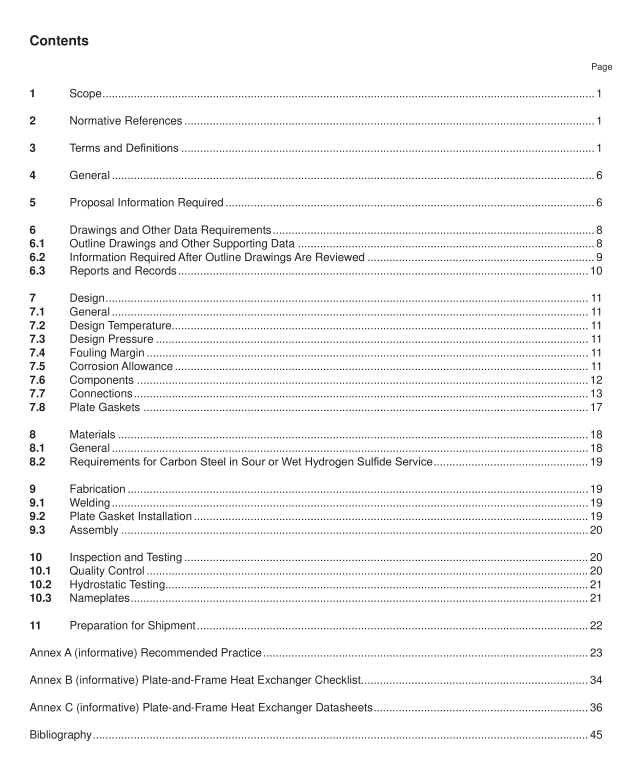
API STD 667 pdf download Plate-and-Frame Heat Exchangers
Scope
This standard gives requirements and recommendations for the mechanical design,materials selection,fabrication,inspection,testing, and preparation for shipment of plate-and-frame heat exchangers for use inpetroleum, petrochemical, and natural gas industries.
lt is applicable to gasketed and semi-welded plate-and-frame heat exchangers.
This document does not cover the requirements for fully welded plate-and-frame , fully welded plate-block, brazedplate, or plate-in-shell heat exchangers.
2Normative References
The following referenced documents are indispensable for the application of this document.For dated references,only the edition cited applies. For undated references, the latest edition of the referenced document (includingany amendments) applies.
NACE MRO103,’ Materials Resistant to Sulfide Stress Cracking in Corrosive Petroleum Refining EnvironmentsNACE MR0175, Petroleum and natural gas industries—Materials for use in H,S containing environments in oiland gas production -Parts 1,2 and 3
NACE SP0472, Methods and Controls to Prevent ln-Service Environmental Cracking of Carbon Steel Weldmentsin Corrosive Petroleum Refining Environments
3 Terms and Definitions
For the purposes of this document. the following terms and definitions apply.3.1
channel
Fluid flow passage created by two adjacent plates.
3.2
cyclic service
Process operation with periodic variation in temperature, pressure,and/or flow rate.
3.3
drip tray
Tray that is able to collect droplets from an entire heat exchanger plate pack.
3.4
end platecover plate
Plate which prevent the fluids in a plate-and-frame heat exchanger from contacting the fixed and movable covers.NOTE There are two end plates, one at each end of the plate-and-frame heat exchanger.
3.5
frame
Assembly that provides the structural support and pressure containment.
NOTE The frame may consist of upper and lower carrying bars, mounting feet, tie bolts, fxed and movable covers, and
a support column.
3.6
heat transfer area
Sum of the surface areas of one side of all plates in contact with both heat-transfer fuids.
NOTE 1 The heat transfer surface area is one side of the plate.
NOTE 2 Areas of end plates are not included.
3.7
heat transfer plate
Sheet of metal precision-pressed or -formed into a corrugated pattern.
NOTE See Figure 1 for plate dimensions, geometry and diagrammatic view of terms used.
3.8
item number
Purchaser’s identifcation number for a heat exchanger.
3.9
liner
A thin alloy sleeve used on port or nozzle components, to isolate the process fuid from the pressure boundary backing material.
3.10
minimum design metal temperature
MDMT
Lowest metal temperature at which pressure-containing components can be subjected to design pressure.
EXAMPLE Ambient temperature or minimum process fuid temperature.
3.11
pass plate
Plate used to change the direction of fow of a stream in a plate-and-frame heat exchanger with two or more passes.
3.12
plate chevron angle
The angle formed between the plate pattern and the line perpendicular to the fow direction.
NOTE 1 For the purposes of this standard the plate chevron angle is as defned above. The user is cautioned however that some vendors and software package suppliers may use a diferent defnition.
NOTE 2 Figure 1 shows a typical heat transfer plate.
