IEEE Std C37.241 pdf download
IEEE Std C37.241 pdf download IEEE Guide for Application of Optical Instrument Transformers for Protective Relaying
4. Introduction
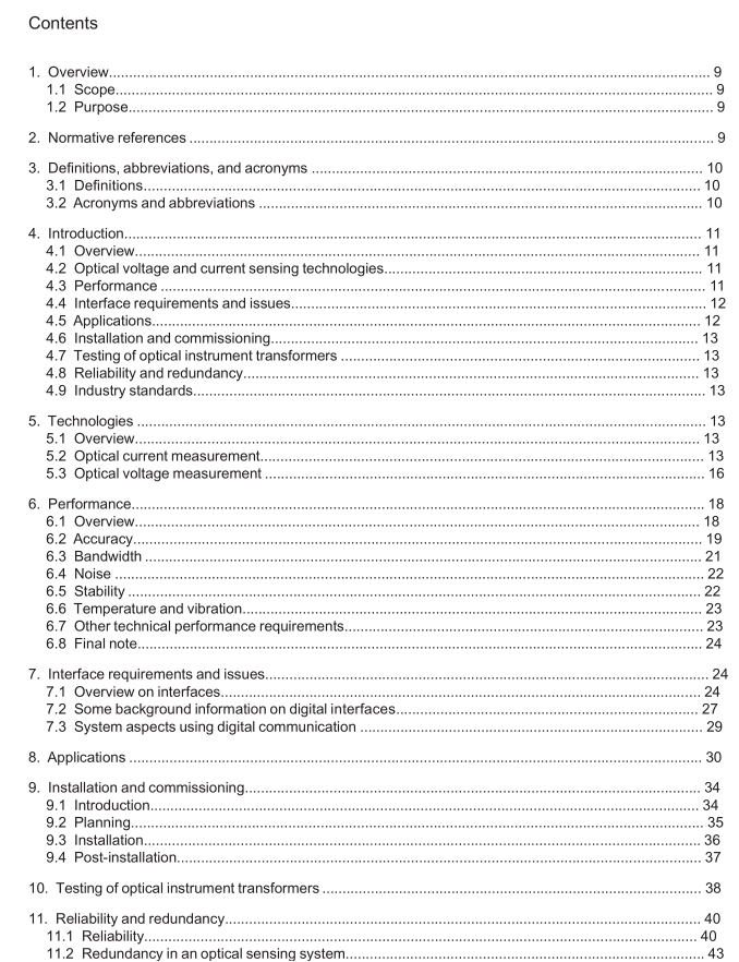
4.1 Overview Optical sensor technology to replace current transformers (CTs) and voltage transformers (VTs) has been demonstrated for over 20 years. These sensors use optics and electronics to achieve accuracy, linearity, dynamic range, and efficient installation far beyond the capabilities of familiar electromagnetic and capacitive instrument transformers. Commercial products have been available for most of that time, with a widening array of choices and manufacturers. However, the commercial transition to new sensors has been gradual, in light of the familiarity and reliability of conventional instrument transformers. Accordingly, the objective of this guide is to provide the reader with a factual understanding of the technical and economic bases for choosing optical instrument transformers (OITs) when familiar sensor technologies remain widely available. This guide provides information on technologies of optical voltage and current sensors, their performance characteristics, their incorporation in measurement systems for protection and control, installation, and maintenance requirements, testing requirements, and application considerations. The following clause outlines the topics covered in detail in the remainder of the guide.
4.2 Optical voltage and current sensing technologies Clause 5 provides a review of the technologies for optical voltage and current sensors in the electric power industry. It introduces the reader to the scientific principles that optical instrument transformers use to measure electrical quantities. It illustrates the product packaging alternatives that arise from these measurement techniques.
4.3 Performance Clause 6 provides a review of technical behavior specifics of optical sensor solutions. Subclauses explain the following features and issues to be considered when using optical sensors:
— Accuracy and dynamic range (6.2)—covering accuracy and linearity of the sensors, including their ability to maintain accuracy over wide ranges of currents or voltages. This subclause lists available accuracy classes. Terminology for newer accuracy class specification (over a wider dynamic range) is reviewed here.
— Bandwidth or frequency response (6.3)—discussing the suitability of optical sensors for capturing transients and measuring harmonic components that ride on power frequency signals. This subclause explains how the sensor electronics and other elements in the measuring chain affect the frequency response of the sensor system.
— Noise and impact of noise on performance (6.4)—the output of all electronic devices, including optical sensor components, contains electrical noise components.This subclause provides an understanding of noise generation, how it can be a positive or negative impact on the performance of a specific function or application, and how to manage it.
— Stability and performance variation over time (6.5)—the components of any device can age and degrade over time. This subclause reviews the aging and possible performance changes of an optical sensor system, as well as mitigation factors and self-monitoring that should be designed into such systems.
— Performance variation over temperature (6.6)—optical-measurement techniques use physical properties of materials which are temperature dependent. A significant challenge in building an effective OIT is to compensate for temperature variations. — Impact of vibration (6.6)—similar to temperature, vibration can have adverse impact on the performance of optical sensors. Mitigating the possible impact of vibration and physical movement is a key part of developing and packaging high-quality OITs.
— Technical requirements for high voltage (HV) substation use (6.7)—as optical instrument transformers have been deployed mostly in high-voltage substations, environmental requirements for HV or extra-high voltage (EHV) power apparatus also apply to optical instrument transformers. These include insulation, load and fault current limits, seismic withstand capability, and electromagnetic compatability(EMC)requirementsfortheassociatedelectronics.Opticalsensorsgenerallyusesimpler HV insulation due to the galvanic isolation provided by optical fibers and the lack of conductive parts in the insulating structure. A key advantage of optical sensors is compactness with superior safety in HV installations. Clause 6 helps the user decide on whether to use optical sensors, what key advantages can be expected, and what design factors and issues have to be accommodated in order to use an optical sensor successfully. Even though this guide focuses on protective relaying applications of optical instrument transformers, the performance characteristics explained here serve as valuable knowledge for use of optical sensors in any applications.
4.4 Interface requirements and issues Clause 7 provides a description of analog and digital output interfaces available for optical instrument transformers, as specified in industry standards. It also explains digital interfaces in the context of IEC 61850 6 , and covers system aspects of digital interfaces.
