ASME B29.300 pdf download
ASME B29.300 pdf download Agricultural, Detachable, and Pintle Chains, Attachments, and Sprockets
1 DEFINITIONS
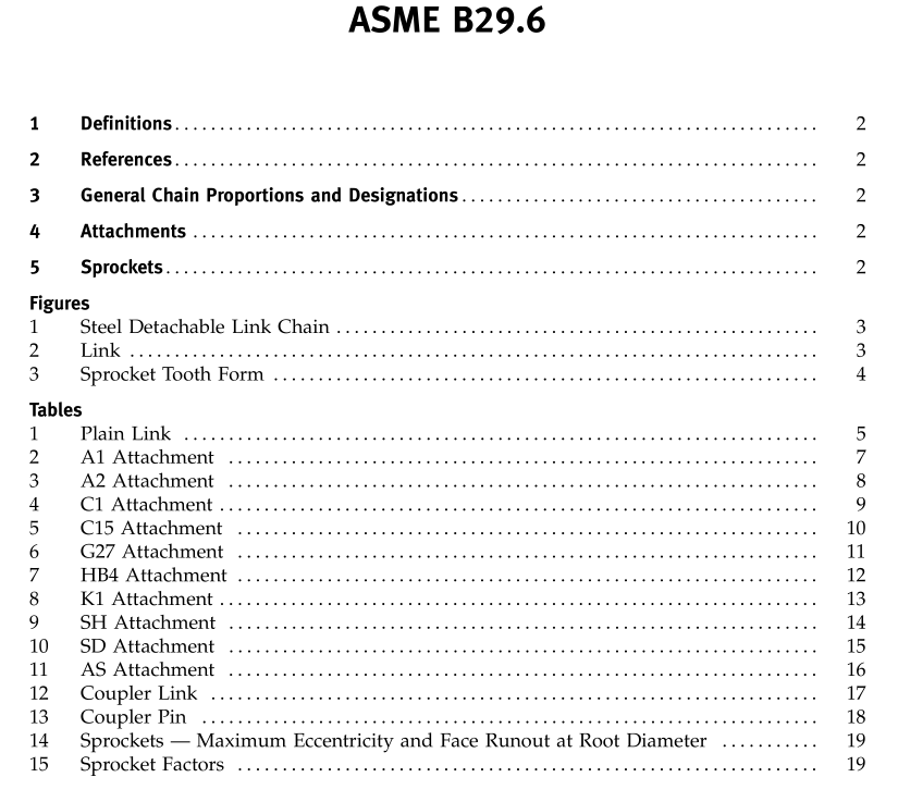
link: a one-piece steel link consisting of end bar A,hook B, and two sidebars C-c (see Fig. 2 of B29.6).neasuring load: the load under which a dry or lightlylubricated chain should be measured for length.
steel detachable link chain: a series of successively assem-bled steel links in which the end bars articulate insidethe hook.The chain is detached by flexing it and drivingthe end bar out of the adjoining hook (see Fig. 1 ofB29.6).
REFERENCES
The following is a list of publications referenced inthis Standard:
Chains for Power Transmission and Material HandlingPublisher: American Chain Association (ACA),6724 Lone Oak Boulevard. Naples,FL 34109(www.americanchainassn.org)
3GENERAL CHAIN PROPORTIONS ANDDESIGNATIONS
3.1 Minimum ultimate Tensile Strength
The Minimum Ultimate Tensile Strength (M.U.T.S.)for chain covered by this Standard is the minimum forceat which an unused, undamaged chain could fail whensubjected to a single tensile loading test.
WARNING:The Minimum Ultimate ‘Tensile Strength is NOTa “working load.” The M.U.T.S. greatly exceeds the maximumforce that may be safely applied to the chain.
(a) Test Procedure.A tensile force is slowly applied, ina uniaxial direction, to the ends of the chain sample.(b)The tensile test is a destructive test. Even thoughthe chain may not visibly fail when subjected to theM.U.T.S., it will have been damaged and will be unfitfor service.
CAUTION: This load is beyond the yield strength of the chainand would render the chain unsuitable for application.
(c) For application guidance, consult the manufactur-ers’ catalogs or the American Chain Association’s hand-book,Chains for Power Transmission and MaterialHandling.
ATTACHMENTS
See Tables 1 through 11 of B29.6 for tolerances anddimensions for the following attachments: plain link,A1,A2,AS,C1,C15,G27,HB4,K1,SD, and sH.
See Table 12 of B29.6 for coupler link information andTable 13 of B29.6 for coupler pin information.
5 SPROCKETS
5.1 General Information
Sprockets for use with steel detachable chains are usu-ally made of cast or wrought ferrous material. Wearresistance is frequently designed into the material of thetooth faces. Sprocket bodies are of many configurations(e.g., plate, arm, web, flat, or dished).When hubs con-taining the sprocket mounting bore are employed, theymay project from either side or from both sides of thesprocket body.
This Standard covers only the dimensions controllingthe surfaces that must properly engage or clear the chain.Dimensions are given in a decimal inch system. Themetric dimensions given are recommended conversionsfrom the decimal inch system. In some cases the conver-sion is not exact; the decimal inch system is thereforeto be taken as the base control dimension.
Sprockets with standard tooth forms are capable oftransmitting chain loads in systems operating under awide variety of conditions such as the followingcombination:
(a) maximum peak tension in chain as great as 0.20of the ultimate breaking strength of the chain;
(b) slack strand tensions as small as 0.25% of theworking tension in the chain;
(c) friction between the chain and the sprocket toothfaces as low as 10%; and
(d) the number of chain links in contact with theperiphery of the sprocket as few as 0.5 × (N- 1).Individually, the above limits are not absolute. Varia-tions may be accepted in each of them provided com-mensurate modifications are made in other limits.5.2 Sprocket Tooth Form
The elements of the tooth profiles for sprockets forstandard chains are given in Fig. 3 and Tables 14 and15 of B29.6.
Maximum tooth thickness t may not exceed (0.95 Dminus actual sideface oscillation), where D equals hookwidth of chain.

