ASME B18.29.1 pdf download
ASME B18.29.1 pdf download Helical Coil Screw Thread Inserts— Free Running and Screw Locking (Inch Series)
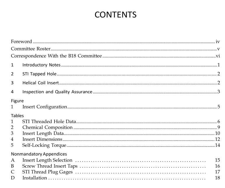
3.4 Configuration and Dimensions Insert configurations shall be in accordance with Fig. 1, and dimensions shall be in accordance with Tables 3 and 4. 3.4.1 Nominal Length. Each nominal insert size is standardized in five lengths which are multiples of the insert’s nominal diameter. These are 1, 1 1 ⁄ 2 , 2, 2 1 ⁄ 2 , and 3 times nominal diameter. Each nominal length is the minimum through-hole length (material thickness), without countersink, into which that insert can be installed. The nominal insert length is a reference value and cannot be measured. 3.4.2 Assembled Length. Actual assembled length of the insert equals nominal length minus 1 ⁄ 2 pitch to minus 3 ⁄ 4 pitch, with insert installed in a basic STI threaded hole. It cannot be measured in the insert’s free state.
4 INSPECTION AND QUALITY ASSURANCE Unless otherwise specified by the purchaser, the inspection of inserts shall be in accordance with ASME B18.18.2 with inspection level 3 for a 15-cycle torque test as described in para. 4.2.3.
4.1 Inspection (Nondestructive)
4.1.1 Examination of the Product. Inserts shall be visually examined for conformance with drawings and workmanship requirements in accordance with ASME B18.18.2.
4.1.2 Threads. The inserts, when assembled in STI threaded holes conforming to Table 1, shall form threads conforming to ASME B1.1, tolerance Class 3B or Class 2B except for the locking feature of screw-locking inserts. The assembled insert, both types, shall accept and function with parts having external UNJ threads per SAE AS8879. NOTE: Accuracy of the finished thread, when the insert is installed, is dependent upon the accuracy of the tapped hole. If the finished tapped hole gages satisfactorily, the installed insert will be within the thread tolerance when the insert meets the requirements of the Standard. It is, therefore, not necessary to gage the installed insert. After the insert is installed, the GO thread plug gage may not enter freely because the insert may not have been fully seated in the tapped hole. However, the insert should become seated after a bolt or screw is installed and tightened.
4.1.3 Tang Removal Notch. The tang removal notch shall be located as shown in Fig. 1 and shall be of such depth that the part may be installed without failure of the tang, and that the tang may be removed, after assembly, without affecting the function of the installed insert.
4.2 Screw-Locking Insert Self-Locking Torque (Destructive) Testing The screw-locking insert, when assembled in threaded holes conforming to Table 1 and tested in accordance with the following paragraphs, shall provide a frictional lock to retain the bolt threads within the torque limits specified in Table 5.
4.2.1 Torque Test Bolts. Assembled screw-locking inserts shall be torque-tested with bolts in accordance with ASME B1.1, cadmium plated, or have other coating with a similar coefficient of friction and a hardness of 36 HRC to 44 HRC. The bolts selected for this test shall be of sufficient length so the thread run out does not enter the insert and that a minimum of one full thread extends past the end of the insert when the bolt is fully seated. Acceptability of bolt threads shall be determined based on System 22 of ASME B1.3 (see Note below). NOTE: Until a replacement for cadmium plating on the torque test bolts (as specified in para. 4.2.1) is found, and test data com- pleted, an alternate coating, lubricant, or both, can be used to perform the torque test (values may be different from those obtained using cad plated screws) based on agreement between the customer and the insert supplier.
4.2.2 Torque Test Block. The insert to be tested shall be installed in a Class 3B threaded hole conforming to Table 1 in a test block made from 2024-T4 (SAE AMS4120, ASTM B 209-02) aluminum alloy. After instal- lation, the tang shall be removed. The surface of the test block from which the insert is assembled shall be marked to indicate the radial location where the assembled insert begins.
4.2.3 Torque Test Method. The torque test shall con- sist of a 15-cycle, room temperature test. A new bolt or screw and a new tapped hole shall be used for each complete 15-cycle test. Bolts must assemble freely, with the fingers, up to the locking coil or coils. The bolt shall be engaged and disengaged from the assembled insert for 15 full installation and removal cycles. The test shall be run at less than 40 rpm to yield a dependable measure of torque and avoid heating of the bolt. A bolt shall be considered fully installed when three threads extend past the end of the locking coils of the insert. The removal cycle shall be considered complete when the locking coils are disengaged.
4.2.3.1 Maximum Locking Torque. Maximum lock- ing torque shall be the highest torque value encountered on any installation or removal cycle and shall not exceed the values specified in Table 5. Maximum locking torque readings shall be taken on the first and seventh installa- tion cycles and on the fifteenth removal cycle.

