ASME B107.300 pdf download
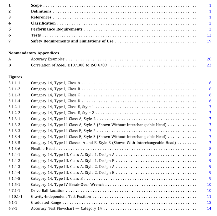
ASME B107.300 pdf download Hand Torque Tools and Torque Testers
4 CLASSIFICATION See Tables 4-1, 4-2, and 4-3.
5 PERFORMANCE REQUIREMENTS Figures are descriptive and notrestrictive. Theyare not intendedtoprecludethemanufactureorpurchaseofother forms oftorque instruments conforming to this Standard. Torque instruments shall pass all applicable tests in section 6. Unless otherwise specified, torque instruments shall be calibrated in the direction(s) of intended use. Torque instruments shall be capable ofbeingcalibrated to the specified accuracy by a method traceable to the National Institute of Standards and Technology (NIST).
5.1 Design — Category 14 Mechanical 5.1.1 Type I, Classes A, B, C, and D — Indicating (a) Operation. Instruments shall indicate torque applied through a deflecting member. They shall operate in both clockwise and counterclockwise directions.
(1) TypeI, ClassesAandB—DeflectingBeam. Flexing ofacantileverbeam connectingthe square driveandhand grip shall provide the basis of operation. Type I, Class A deflectingbeamtorque instruments maybesimilarto that shown in Figure 5.1.1-1. Type I, Class B deflecting beam torqueinstruments maybesimilarto thatshowninFigure 5.1.1-2.
(2) Type I, Classes C and D — Rigid Housing. The deflecting member and dial mechanism shall be enclosed within the rigid housing. The pointer and dial face shall be protected by a transparent cover that shall be so located and constructed as to be reasonably free from accidental damage resulting from being struck or abraded. Type I, Class C rigid housing torque instruments may be similar to that shown in Figure 5.1.1-3. Type I, Class D rigid housing torque instruments may be similar to that shown in Figure 5.1.1-4.
(3) Type I, Classes B and D — Interchangeable Head Connection forAdaptersandExtensions. Thetorque instru- ment shall be equipped with a connection, suitable for accepting a variety of mating wrenching heads. The connection and standard wrenching heads shall be designed so that the requirements of para. 5.10 are met throughout the specified accuracy range. The wrenching heads shall comply with the requirements ofpara.
5.7. Indicating torque instruments with an interchangeable headmaybe similarto Figure 5.1.1-2 (Class B) or Figure 5.1.1-4 (Class D).
(b) Indicator. A dial or scale shall be located to permit convenient and accurate reading. The graduation marks shall be colored and shaped to be distinctand easily read. Thewidthofthegraduationmarkshallnotbegreaterthan one-halftheadjacentspacewidth.Thewidthofthepointer tip or indicator line shall not be greater than the widest graduation mark, nor shall the pointer completely cover any graduation mark on the outer scale. The pointer shall be located close to the scale face to meetthe parallaxerror requirements of para 6.2.
(c) Hand Position. If, in order to achieve the required accuracy,itisnecessarytoapplytheloadataspecificpoint on the hand grip, a pivot shall be located at that point.
(d) Auxiliary Functions. Additional features may be incorporated on the torque instrument to improve accu- racyorusefulness. The inclusion ofsuch features shall not becauseforrejectionofthetorqueinstrumentprovidingit conforms to the performance requirements of this Standard.
(e) TypeI, ClassesA, B, C, andD, Style1 —Plain Scale. No auxiliary operational features are required.
(f) Type I, Classes A, B, C, and D, Style 2 — Scale With Signal Mechanism. A signal mechanism capable of being adjustedwithoutthe useoftools to anygraduated value of the instrumentshall be provided. The signal shall operate automatically within the accuracy requirements of this Standard. (g) Type I, Classes A, B, C, and D, Style 3 — Scale With Memory Indicator. An auxiliary pointer or other device capable of retaining an indication of the maximum torque transmitted through the instrument shall be provided. The auxiliary pointer shall function at any graduated torque value within the accuracy requirements of this Standard. Means shall be provided for resetting the auxiliary pointer. Normal handling of the instrument shall not cause the auxiliary pointer to be displaced.
5.1.2 Type I, Class E — Indicating, Screwdriver Grip. The grip and drive shall lie on the same axis ofrotation to allow the instrument to be used like a screwdriver. Instruments shall be limited to a capacity of100 lbf-in. (11.3 N•m), and those with capacities over 40 lbf-in. (4.5 N•m) shallbeequippedwithauxiliarydrivingmeans,such as a T-handle.

