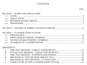
AS NZS 61058.1.1 pdf download – Switches for appliances Part 1.1: Requirements for mechanical switches (IEC 61058-1-1:2016 (ED.1.0) MOD)
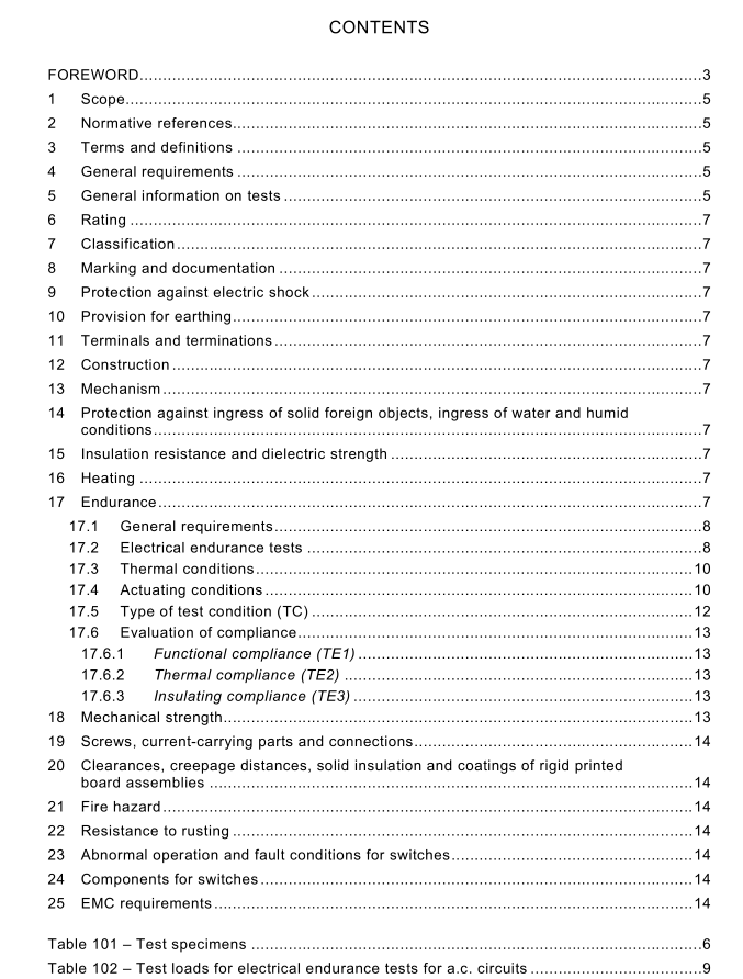
AS NZS 61058.1.1 pdf download Switches for appliances Part 1.1: Requirements for mechanical switches (IEC 61058-1-1:2016 (ED.1.0) MOD)
17.1General requirements
17.1.1 Switches shall withstand without excessive wear or other harmful effect theelectrical,thermal and mechanical stresses that occur in normal use.
17.1.2 The sequence of tests to be completed on the same 3 specimens is as follows:
– TC3: a test at high speed specified in 17.5.3; this test only applies to switches with morethan one pole,and where the type of connection is of polarity reversal;
– TC2: a test at slow speed specified in 17.5.2,
– TC1: an increased-voltage test at accelerated speed as specified in 17.5.1; this test does
not apply to switches classified according to 7.2.9;
TC9: a locked-rotor test as specified in 17.5.5 at accelerated speed; this test only appliesto switches classified according to 7.2.9;
– TC4: a test at accelerated speed as specified in 17.5.4;followed by the requirements of 17.6.
NOTE The different types of tests are specified in 17.5.
17.1.3 When required by Clause 13, the following test, TC10, is conducted on a different setof 3 specimens:
-TC10: a test at very slow speed as specified in 17.5.6; this test only applies to switches
according to the requirements of 13.1.
The manufacturer may choose to complete TC10 in the sequence of 17.1.2 in place of TC2.Compliance is checked by 17.6.1(TE1) and 17.6.3 (TE3).
17.2Electrical endurance tests
The switch shall be loaded as specified in Table 102 and/or Table 103 and connected inaccordance with the circuit as given in 61058-1:2016, Table 2.
a) Where,in lEC 61058-1:2016,Table 2, an auxiliary switch (A) is symbolized in the testcircuit, the tests for the two ON-positions of the specimen (S) are performed on twoseparate sets of test samples.The connection to the test load to be performed for the twotests is symbolized in lEC 61058-1:2016,Table 2 by an auxiliary switch A.
b) Multiway switches are loaded according to 61058-1:2016,Table 1. The load for the other
switch positions is that resulting from the loads necessary to achieve the conditionsspecified above.
c) For circuits according to 7.2.7 for specific lamp load,, the connection and test load are as
specified by the manufacturer using the maximum occurring inrush current at roomtemperature.For a specific lamp load, it is recommended that the specimen be operatedwith loads that are used in the field rather than with synthetic loads.Forced cooling of thespecific lamp load may be applied in order to ensure cold resistance for each operatingcycle and shorten the test time.
d) No electrical load is applied during the endurance tests for switches classified to 7.2.6
with a rating of 20 mA or less.
1 7.3 Thermal conditions
1 7.3.1 For switches according to 7.3.2, during the tests in 1 7.5.4 (TC4) all parts are exposed to temperatures as follows: – For the first half of the test period at maximum air temperature (T +5/0) °C. – For the second half of the test period at 25 °C ± 1 0 °C or at the minimum air temperature (T 0/-5) °C if T is less than 0 °C.
1 7.3.2 For switches according to 7.3.3, during the tests in 1 7.5.4 (TC4), those parts that are declared for use at 0 °C to 55 °C shall be exposed to a temperature within this range for the complete test period.
– For the first half of the test period, the air temperature of the remainder of the switch shall, be maintained at the maximum air temperature (T +5/0) °C.
– For the second half of the test period the tests are carried out at 25 °C ± 1 0 °C or at the minimum air temperature (T 0/-5) °C if T is less than 0 °C.
1 7.3.3 For switches according to 7.3.1 , during the tests in 1 7.5.4 (TC4), the switch shall be exposed to an air temperature of 25 °C ± 1 0 °C.
1 7.4 Actuating conditions
1 7.4.1 The switches are operated by means of their actuating member either manually or by an appropriate apparatus which is arranged to simulate normal actuation.
The operating speed for the operating cycles shall be as follows:
For the tests of mechanical switches:
a) for very slow speed:
– approximately 1°/s for rotary actuation;
– approximately 0,5 mm/s for linear actuation.
