AS IEC 62217 pdf download – Polymeric HV insulators for indoor and outdoor use — General definitions, test methods and acceptance criteria
AS IEC 62217 pdf download – Polymeric HV insulators for indoor and outdoor use — General definitions, test methods and acceptance criteria
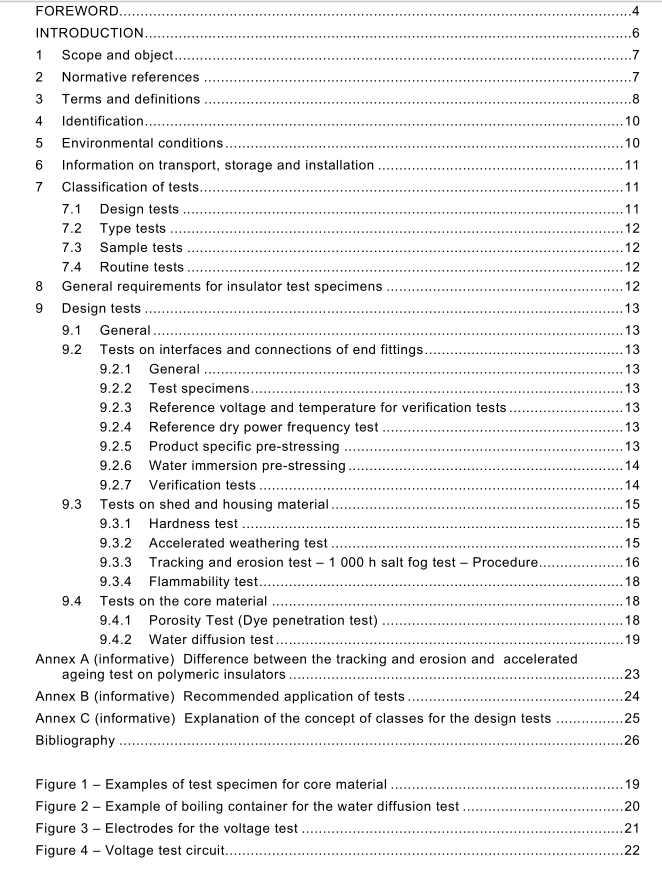
9 Design tests
9.1 General
The following tests are normally classified as design tests, unless otherwise specified in the relevant product standard. The design tests shall be performed only once according to the relevant product standard and the results shall be recorded in a test report. Each test (9.2, 9.3and 9.4) can be performed independently on new test specimens where appropriate, according to the test sequence given in the relevant test standard. The polymeric insulator of a particular design shall be deemed qualified only when all insulators or test specimens pass all the design tests specified in the relevant product standard.
9.2 Tests on interfaces and connections of end fittings
9.2.1 General
The test sequence consists of:
• reference dry power frequency test
• pre-stressing
• verification test
9.2.2 Test specimens
For this series of tests insulators assembled on the production line shall be selected. The number of specimens and their dimensions shall be according to the relevant product standard. They shall be checked and tested as indicated in Clause 8. If the manufacturer only has facilities to produce insulators with one or more dimensions smaller than indicated in the relevant product standard, the design tests may be performed on insulators of those dimensions available to him, however the results are only valid for other insulators of the same design class up to the dimensions tested.
9.2.3 Reference voltage and temperature for verification tests For time or economic reasons the reference power frequency test in 9.2.4 at the beginning of the test sequence may be omitted if an additional reference test specimen conforming to 9.2.2 is used. The power frequency voltages after pre-stressing according to 9.2.7.4 and the shank temperature shall be compared either with the values of the reference test specimen or with the voltages determined prior to pre-stressing. It is clearly understood that the reference test specimen shall be not submitted to pre-stressing.
9.2.4 Reference dry power frequency test The reference dry power frequency external flashover voltage shall be determined by averaging five flashover voltages determined according to IEC 60060-1 on the test specimens or on the reference test specimen. This average flashover voltage shall be corrected to standard conditions in accordance with IEC 60060-1 . The flashover voltage shall be obtained by increasing the voltage linearly from zero to flashover within 1 min.
9.2.5 Product specific pre-stressing The test specimens shall be subjected to pre-stressing (e.g. thermal-mechanical) according to the relevant product standard.
9.2.6 Water immersion pre-stressing The specimens shall be kept immersed in a vessel, in boiling de-ionized water with 0,1 % by weight of NaCl, for 42 h. Alternatively, tap water may be used with salt added to obtain a conductivity of 1 750 µS/cm ± 80 µS/cm at 20 °C. For a different water temperature, the conductivity correction as given in IEC 60507:1 991 , Clause 7 shall be applied. At the end of boiling, the specimens are allowed to cool and shall remain in water until the verification tests start in the following sequence. If transport is necessary in this period, the wet insulators may be put in sealed plastic bags or another suitable container for a maximum of 1 2 h.
9.2.7 Verification tests
9.2.7.1 General
The time interval between the following individual tests shall be such that the verification tests are completed within 48 h.
9.2.7.2 Visual examination
The housing of each specimen is inspected visually. No cracks are permissible.
9.2.7.3 Steep-front impulse voltage test
9.2.7.3.1 Procedure
The test specimens shall be fitted with sharp-edged electrodes (consisting of clips, e.g. made of a copper strip approximately 20 mm wide and less than 1 mm thick). These electrodes are fitted firmly around the housing between sheds so positioned to form sections of axial length of about 500 mm or smaller. The voltage shall be applied to the original metal fittings in case of insulators with a distance between end fittings smaller than, or equal to, 500 mm. An impulse voltage with a steepness of at least 1 000 kV/µs shall be applied between two neighbouring electrodes or between the metal fitting and the neighbouring electrode respectively. Each section shall be stressed individually with 25 impulses of positive and 25 impulses of negative polarity. Means shall be employed to prevent internal flashover of hollow insulators.
