API TR 6AF3 pdf download
API TR 6AF3 pdf download High-pressure High-temperature (HPHT) Flange Design Methodology
Scope
The scope of this document is to provide design guidelines for AP1 6BX style flanges utilized as end and outletconnectors in high-pressure, high-temperature (HPHT) surface and subsea applications. For this document,HPHT applications are intended to mean Flanges assigned a temperature rating greater than 350° F or apressure rating greater than 15,000 psi.
The current version of this guideline does not address thermal effects including gradient effects or subseaproduction equipment. Service temperature ratings above 550 °F(288 C) are outside the scope of this technical
report. The flange designer should address thermal effects when designing flanges rated for high temperatures.
2Normative References
The following referenced documents are indispensable for the application of this document.For dated references,only the edition cited applies. For undated references, the latest edition of the referenced document (includingany amendments) applies.
API Specification 6A,Specification for Wellhead and Trec EquipmentAPI Standard 6x,Design Calculations for Pressure-containing Equipment
API Technical Report 6AF,Technical Report on Capabilities of API Flanges under Combinations of Load
APl Technical Report 6AF1,Technical Report on Temperature Derating on APl Flanges under Combination ofLoading
APl Technical Report 6AF2,Technical Report on Capabilities of APl Integral Flanges under Combination ofLoading—-Phase i
ASME Boiler and Pressure Vessel Code Section VIlI, Division 2—Alternative Rules
ASME Boiler and Pressure Vessel Code Section vII, Division 3—Alternative Rules for Construction of HighPressure vessels
Robert Eichenberg, “Design Considerations for AWHEM 15,000 psi,” ASME Paper 57-PET-23,1957
Robert Eichenberg, ” Design of High-Pressure Integral and Welding Neck Flanges with Pressure-Energized RingJoint Gaskets,Journal of Engineering for Industry,1964
Joe R.Fowler,”Sealability of API R, RX & BX Ring Gaskets,” PN 90-21, Stress Engineering Services,Ilnc..Report prepared for APl,January 1994
3Terms,Definitions, Acronyms, Abbreviations,and Symbols
3.1 Definitions
For the purposes of this document, the following definitions, and those definitions in APl 6A, apply.3.1.1
Stiffness ratio
Stiffness of the bolt divided by the stiffness of the bolt plus the stiffness of the flange body.NOTE Refer to Section B.2.5.
3.2 Acronyms, Abbreviations, and Symbols
For the purposes of this document, the following abbreviations apply.
FEA fnite element analysis
G groove
H height
HPHT high-pressure high-temperature
ID inner diameter
LRFD load and resistance factor design
OD outer diameter
P working pressure
σ allow allowable stress
σ hoop hoop stress at working pressure
Sm Design Stress
KB Stifness of Bolt
KJ Stifness of Flange Body
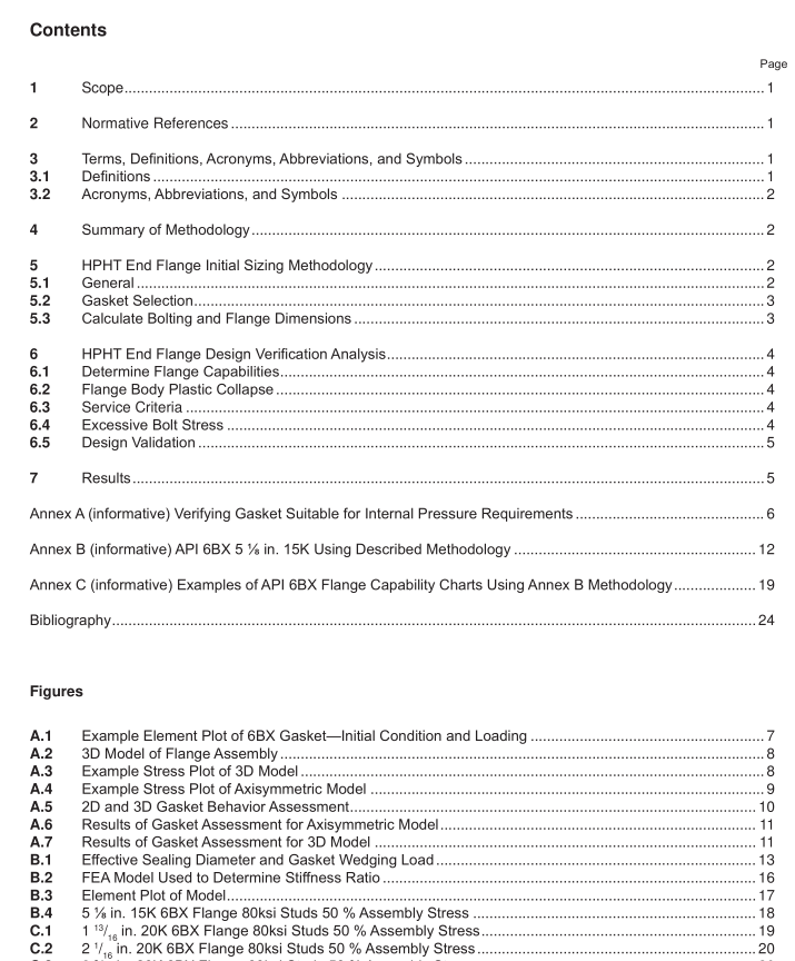
4 Summary of Methodology
The methodology is comprised of four distinct phases:
1 ) Select a gasket for the internal pressure requirements
2) Calculate the bolting and fange dimensions
3) Determine the fange’s capabilities with regards to pressure, bending and tension loading
4) Validate the fange design in accordance with an industry accepted specifcation.
Loading conditions addressed by this guideline are pressure and bending. Loading conditions not addressed by this guideline include torsion, transverse shear, thermal gradients, and tension.
Failure modes addressed by this guideline are fange body plastic collapse, fange body excessive deformation,and bolt failure under monotonic (as opposed to cyclic) loading conditions.
Failure modes not verifed by the guideline include leakage, local strain and fatigue. According to PN 90-21, API 6BX fanges (or bolting) will likely be overstressed before 6BX gasket leakage. For this reason, this document does not assess the 6BX gaskets for leakage. This is based on 6BX gaskets maintaining critical sealing contact stress after hub-separation. It assumes that pressure is applied prior to external loading. These fndings were supported by validation testing on 4 1 / 1 6 and 7 1 / 1 6 6BX fanges. Application where fanges are subjected to external loading prior to pressurization may require additional considerations.
5 HPHT End Flange Initial Sizing Methodology
5.1 General This section provides guidance on how to develop the initial sizing of an API 6BX style fange using traditional hand calculations. These calculations should not be considered as a requirement during the verifcation process. Furthermore, use of these calculations do not exempt verifcation and validation of the fnal design.
