API TR 10TR5 pdf download
API TR 10TR5 pdf download Methods for Testing of Solid and Rigid Centralizers
2.3 Solid Centralizer This centralizer is manufactured with rigid, non-flexible blades or bands. The centralizers have solid bodies and solid blades. The blades are either formed during molding of the centralizer or welded on the solid body. These devices have a smaller OD than the casing or hole where the centralizers will be used, and, therefore, generate zero starting forces. Because these devices have a solid body, they do not experience deformation when run through restrictions; they do not flex.
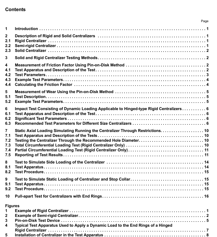
3 Solid and Rigid Centralizer Testing Methods
The following measurement and test procedures are included in this document:
1 . measurement of friction factor using the pin-on-disk method (Section 4);
2. measurement of wear using the pin-on-disk method (Section 5);
3. impact test consisting of dynamic loading applicable to hinge-type rigid centralizers (Section 6);
4. static axial loading to simulate running through restrictions (Section 7);
5. test to simulate side loading of the centralizer (Section 8);
6. test to simulate static loading of the centralizer and stop collar (Section 9);
7. pull-apart test for rigid centralizers with end rings (Section 1 0).
The user is encouraged to select the applicable measurements and tests for solid or rigid centralizers appropriate for specific well conditions.
4 Measurement of Friction Factor Using the Pin-on-Disk Method
4.1 Test Apparatus and Description of the Test
The friction factor of centralizer construction materials can be measured in the presence of different mud systems using the “pin-on-disk” device and method (see Figure 3). For the results to be relevant, materials being tested should match the composition of the construction materials used to manufacture the centralizers. The device is composed of a stationary base element (pin) on which the test specimen is mounted and a rotating disk. The specimen to be tested and the disk are pressed together using a calculated force corresponding to the anticipated force on the centralizer.
The sliding velocity and the pressing force can be adjusted and controlled over wide ranges. The area of the disk contacted by the specimen is continuously sprayed with the mud being used during the test. When measuring friction factors using different mud systems or different centralizer materials, the geometry and test conditions for all tests must be identical. During the tests, the amount of fluid flow must be regulated to ensure the surfaces of the disk and the specimen are always covered with the fluid. Table 1 , Section 4.3 lists examples of parameters used to conduct a test and is not a specific recommendation. In addition to the composition of the materials used in the test, other important parameters to consider include: velocity, pressure, temperature and rotating time. Friction factor results from this test are not usable in the field. Many other parameters and conditions affect actual field-obtained friction factors; however, results from this test method may be used to compare different centralizer materials and drilling fluids under “identical” test conditions.
4.2 Test Parameters 4.2.1 Material Composition Composition of the materials used to simulate the centralizer (specimen) and the formation or the casing (rotating disk) will affect test results. Therefore, the specimen material must match that of the centralizer being tested. The disk material should simulate the casing or formation being considered. The materials must be kept consistent within a test series to allow data comparison.
4.2.2 Disk Speed or Sliding Velocity The disk speed will affect the friction observed during the test. The velocity should match that found in field conditions when running casing. If it is assumed the running speed for the casing is one joint per minute, then disk speeds of 30 ft/min to 40 ft/min would be appropriate. Velocity will be affected by the disk diameter and the location of the specimen on the disk.
4.2.3 Normal Force The loading force of the specimen on the disk must be consistent within a series of tests. The normal force is a critical test parameter must be calculated to correspond to forces on the centralizer while being run and must be carefully controlled.
4.2.4 Specimen Geometry For comparative purposes, the geometry of the specimen must be carefully controlled. A change in the specimen geometry will affect the contact area and the result of the test.
4.2.5 Temperature and Fluid Lubrication Consistent fluid lubrication of the sample during the test and consistent fluid temperatures should be controlled. Fluid lubricity can change with temperature and will affect the result of the test.
