API TR 10TR4 pdf download
API TR 10TR4 pdf download Selection of Centralizers for Primary Cementing Operations
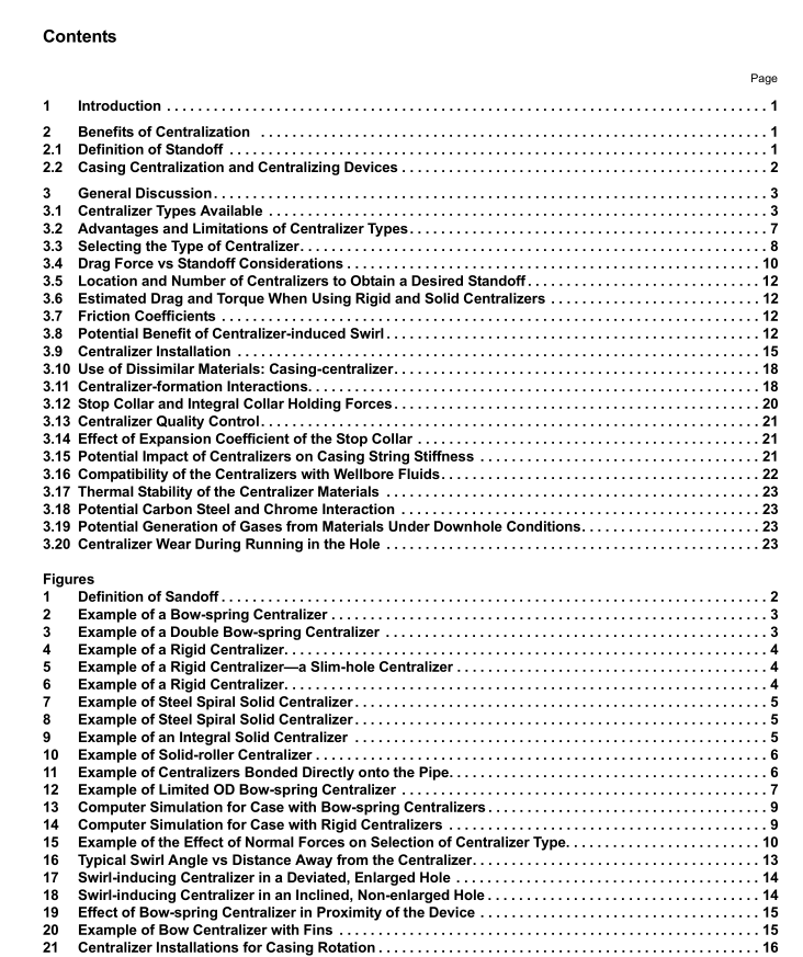
3.2 Advantages and Limitations of Centralizer Types
3.2.1 Bow-spring
1 . This centralizer type has the ability (flexibility) of adjusting to varying hole sizes (can potentially maintain standoff even in irregular size holes).
2. Certain designs incorporate fins to induce swirl (turbulence).
3. Because of the spring bows, these centralizers tend to exhibit high starting and running forces.
4. In highly deviated or horizontal wellbores, improper use of these devices may prevent the casing from getting to bottom.
5. If the centralizer becomes stuck, it may break or the stop rings may slip, potentially forming a “nest” of centralizers.
6. These devices may not provide desired standoff under high lateral load conditions.
3.2.2 Rigid
1 . Because they cannot be collapsed by normal forces generated in the hole, they can ensure a minimum standoff in high normal force situations (provided there is minimum embedment in the borehole wall), such as across severe doglegs and high angle or horizontal wells.
2. Running forces are generally much lower than for bow-spring centralizers.
3. The starting forces are zero.
4. By design, solid centralizers have a fixed OD. They do not adjust to varying (large) hole sizes.
5. Some designs allow for deformation of the fins to help run the centralizer through hole restrictions.
6. If the centralizer becomes stuck, it may break or the stop rings may slip, potentially forming a “nest” of centralizers.
7. Several designs include spiral blades to induce turbulence around the devices.
8. Some designs provide low restriction to flow.
3.2.3 Solid
1 . Because they cannot be collapsed by normal forces generated in the hole, they can ensure a “minimum” standoff in high normal force situations (provided there is minimum embedment in the borehole wall), such as across severe doglegs and high angle or horizontal wells.
2. Running forces are generally much lower than for bow-spring centralizers.
3. The starting forces are zero.
4. By design, they have a fixed OD. The devices cannot adjust to varying (large) hole sizes.
5. The designs do not allow for deformation to help run the centralizer through hole restrictions. If the centralizer becomes stuck, it may break or the stop rings may slip, potentially forming a “nest” of centralizers.
6. Several designs include spiral blades to induce swirl flow around the devices. 7. Some solid designs may present high restrictions to flow. Care should be exercised when using them in narrow annuli.
3.3 Selecting the Type of Centralizer The selection of the proper centralizer for a particular well application is a critical engineering consideration. The goal of the centralizer program should be to optimize the centralization of the casing in the wellbore to aid in proper mud removal and achieve zonal isolation. Depending on a number of design criteria, the proper centralizer for a particular application may be a bow-spring, rigid, or solid centralizer.
In any given well, there can be application for all three types of centralizers, and only by evaluating all available data can the proper centralizer(s) be selected. Not all centralizers available to operators are of high quality, and the user is cautioned to consider construction quality of the device when selecting a centralizer. There are API/ISO documents available with methods to test the quality of bow-spring centralizers (i.e. ISO 1 0427-2). Similarly, API TR 1 0TR5 defines additional methods to test the quality of rigid or solid centralizers. Bow-spring centralizers are commonly used in cementing operations and can provide a high level of standoff. Double-bow centralizers can also offer good standoff with reduced levels of running forces. There are many situations where bow-spring centralizers will not perform as required because of large normal and/or running forces, such as found in high dogleg situations. For these circumstances and for complicated well paths (high deviations, high angle change, severe doglegs, extended reach, S-shapes, etc.) the use of solid or rigid centralizers may be required. The selection of centralizer type (or combination of centralizers) should be made using a centralizer placement simulator for the actual condition of the well. Torque forces and drag (total running forces) should be calculated, as well as the standoff, up and down the entire hole using the actual hole deviation and caliper data.
The properties (running, restoring forces, etc.) of the centralizers being considered should be used in the calculations. Table 1 gives parameters used in examples of computer-generated simulations (see Figures 1 3 and 1 4). The first example shows a case in which the pipe could not be run to bottom because of the elevated drag generated by bow- spring centralizers. The second example shows that a rigid centralizer would allow the pipe to get to bottom. The centralizer of choice to use in this case is a rigid centralizer.
