API St 609 pdf download
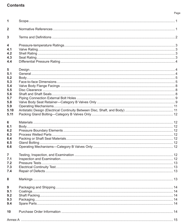
API St 609 pdf download Butterfy Valves: Double-fanged, Lug- and Wafer-type, and Butt-welding Ends
1.1 This standard covers design,materials,face-to-face dimensions, pressure-temperature ratings,andexamination, inspection, and test requirements for gray iron, ductile iron, bronze, steel, nickel-based alloy, orspecial alloy butterfly valves.
1.2 The following two categories of butterfly valves are included:
a) Category A—Manufacturer’s rated cold working pressure (CWP) butterfly valves, usually with a concentric
disc and seat configuration. Sizes covered are NPs 2 to NPs 60 for valves having ASME class 125 or class150 flange bolting patterns.
b) Category B—ASME class and pressure-temperature-rated butterfly valves that have an offset seat and
either an eccentric or a concentric disc configuration.Sizes covered are listed below:
– for lug and wafer, class 150 and 300: NPS 2 to NPS 60;
– for lug and wafer, class 600: NPS 3 to NPS 60;
— for double-flanged short and long pattern, class 150,300, and 600:NPS 3 to NPS 60;
— for butt-welding ends, class 150,300 and 600: NPS 3 to 6o;
lnformation to be specified by the purchaser is shown in Annex B.
1.3Valve configurations include double-flanged, lug- and wafer-type with facings that permitinstallation betweenASME and MSs flanges and butt-welding ends. Configurations conform to the standards and specificationslisted in Section 2.Typical valve construction and nomenclature for valve parts are shown in Annex C.
2Normative References
The following documents are referred to in the text in such a way that some or all of their content constitutesrequirements of this document. For dated references, only the edition cited applies. For undated references, thelatest edition of the referenced document (including any addenda) applies.
API Standard 598,Valve Inspection and Testing
API Standard 607, Fire Test for Quarter-turn Valves and Valves Equipped with Nonmetallic Seats
API Standard 641,Type Testing of Quarter-turn Valves for Fugitive Emissions
ASME B1.11 ,Unified Ilnch Screw Threads (UN,UNR, and UNJ Thread Forms)
ASME B16.5, Pipe Flanges and Flanged Fittings: NPS 1/2 through NPS 24,Metric/Inch Standard
ASME B16.24,Cast Copper Alloy Pipe Flanges, Flanged Fittings, and Valves: Classes 150,300, 600,900,1500and 2500
ASME B16.25,Buttwelding Ends
ASME B16.34,Valves—Flanged,Threaded,and Welding End
ASME B16.42,Ductile lron Pipe Flanges and Flanged Fittings: Classes 150 and 30o
ASME B16.47,Large Diameter Steel Flanges: NPS 26 Through NPS 60 Metric/Inch StandardASME B31.3,Process Piping
ASME B36.10M,Welded and Seamless Wrought Steel Pipe
MSS SP-6? , Standard Finishes for Contact Faces of Pipe Flanges and Connecting-end Flanges of Valves andFittings
ANSIMSS SP-25, Standard Marking System for Valves, Fittings, Flanges, and UnionsMss SP-45,Bypass and Drain Connections
Mss sP-91,Guidelines for Manual Operation of Valves
ANSIMSS SP-134,Valves for Cryogenic Service, Including Requirements for Body/Bonnet Extensions
ANSI/NACE MRO1033ISO 17945, Petroleum, Petrochemical and Natural Gas Industries—Metallic MaterialsResistant to Sulfide Stress Cracking in Corrosive Petroleum Refining Environments
ANSINACE MRO175ISO 15156, Petroleum and Natural Gas Industries—Materials for Use in H2S-containingEnvironments in Oil and Gas Production
3Terms and Definitions
For the purpose of this document, the following terms and definitions apply.
3.1
Class
An alphanumeric designation that is used for reference purposes relating to valve pressure-temperature capability,taking into account valve material mechanical properties and valve dimensional characteristics. It comprises theletters “Class” followed by a dimensionless whole number. The number following the letters “Class” does notrepresent a measurable value and is not used for calculation purposes except where specified in this standard.The allowable pressure for a valve having a class number depends on the valve material and its applicationtemperature and is found in tables of pressure-temperature ratings.
3.2
cryogenic service
Unless a different temperature is specified by the purchaser,valves required to operate at or below -73 cC(-100 °F) are in cryogenic service.
3.3
dead-end service
A condition that may occur after the companion flange and/or piping are removed from one side of a valve.
3.4
NPS
An alphanumeric designation of size that is common for components used in a piping system, used for referencepurposes, comprising the letters “NPS” followed by a dimensionless number indirectly related to the physical sizeof the bore or outside diameter of the end connection as appropriate.The dimensionless number may be used as
