API 600 pdf download
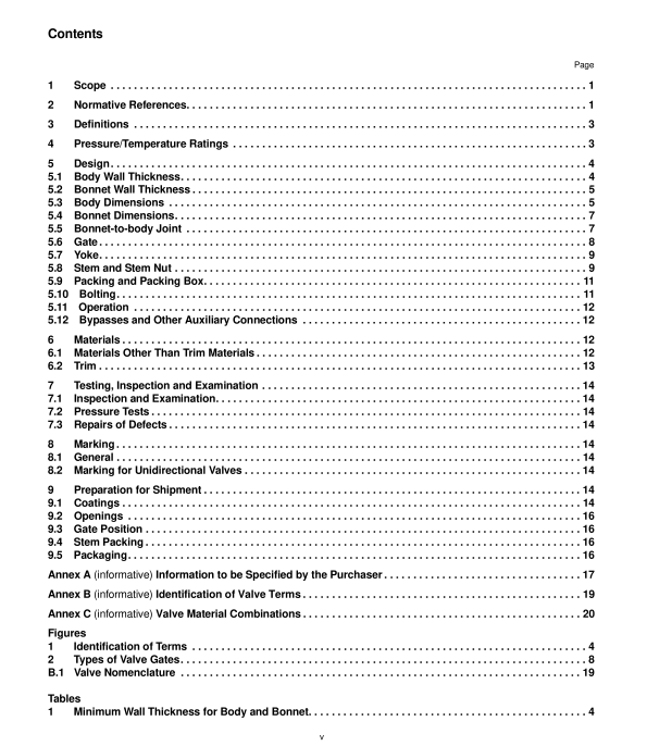
API 600 pdf download Steel Gate Valves—Flanged and Butt-welding Ends, Bolted Bonnets
5.9.2 The nominal depth of the packing box shall accommodate a minimum of five uncompressed rings of packing.Unless otherwise specified by the purchaser, the packing box surface area in contact with the packing material shallhave a surface finish, Ra, of 175 uin. (4.5 um) or smoother.
5.9.3 The nominal bore (inside diameter) of the packing box shall be the sum of the nominal valve stem diameter plustwice the nominal packing width plus a clearance factor, , i.e.equal to d,+ 2w + y. See Table 6 for the required values.
5.9.4 A gland and a separate gland flange shall be provided for packing compression. The gland flange shall havetwo holes to receive the gland bolting. Slots for gland flange bolts shall not be used.The gland and gland flange shallbe self-aligning. The gland shall have a shoulder at its outer edge so as to prevent complete entry of the gland into thepacking box.
5.9.5 Alantern ring shall be provided only if so specified by the purchaser. In order to accommodate the lantern ring,the packing box depth shall be at least equivalent to that of a minimum of three uncompressed rings of packing abovethe lantern ring and three uncompressed rings of packing below the lantern ring plus the length of the lantern ring.
5.9.6 The clearance between the packing box bore (inside diameter) and the outside diameter of the gland (seeFigure B.1) shall be nominally less than the diametrical clearance between the inside diameter of the gland and thestem diameter.
5.10Bolting
5.10.1 Bolting shall be standard inch series bolting, except if the purchaser specifies metric series bolting. Bolting forthe bonnet-to-body joint shall be continuously threaded stud bolis with heavy, semi-finished hexagon nuts that are inaccordance with ASME B18.2.2 or ASME B18.2.4.6M.
5.10.2Yoke-to-bonnet boting shall be either continuously threaded stud bolts or headed bolts with hexagon nuts.5.10.3 Gland bolts shall be hinged eyebolts, headed bolts, stud bolts or studs. Hexagon nuts shall be used.
5.10.4 Bolting with diameters 1 in.(25 mm) and smaller shall have coarse (UNC) threads or the most nearlycorresponding metric threads. Bolting with diameters larger than 1 in.(25 mm) shall be 8-thread series (8UN) or themost nearly corresponding metic threads. Bolt threads shall be Class 2A and nut threads shall be Class 2B, inaccordance with ASME B1.1.Studs used for gland bolting shall use a Class 5 interference fit conforming toASME B1.12.When metric bolting is used metric bolt threads shall be tolerance Class 6g and nuts tolerance Class6H in accordance with ASME B1.13M.
5.11Operation
5.11.1 Unless otherwise specified by the purchaser, the valve shall be supplied with a direct operated handwheelthat opens the valve when turned in a counter-clockwise direction.
5.11.2 The handwheel shall be a spoke-rim type with a maximum of six spokes and shall be free from burrs andsharp edges.Unless otherwise specified, the handwheel shall be a one-piece casting or forging or a multi-piececarbon steel fabrication that includes other carbon steel product forms. Fabricated handwheels shall have strengthand toughness characteristics comparable to that of handwheels made as one-piece castings or forgings.
5.11.3 The handwheel shall be marked with the word “OPEN” and an arrow pointing in the direction of opening.except when the handwheel size makes such marking impractical.
5.11.4 The handwheel shall be retained on the stem nut by a threaded handwheel nut.
5.11.5 lf operation by a chain wheel, gearbox or power actuator is to be added to the valve, the purchaser shallspecify the following, as applicable:
– for chainwheel operation, the dimension from the centerline of the valve stem to the bottom of the chain loop;
-spur or bevel gear and the position of gearing handwheel relative to the pipe axis;
-electric, hydraulic, pneumatic or other actuator type;
maximum service temperature and pressure differential across the valve disc;
-power supply attributes for power actuators.
5.11.6 Valve-to-gear-box or power actuator flange mating dimensions shall be according to lS0 5210 or shallcomply with the purchaser’s specifications.
5.12 Bypasses and Other Auxiliary Connections
Auxiliary connections to the body and/or bonnet, such as drains shall be furnished only if specified on the purchaseorder. The design and construction of the joint and the piping of auxiliary connections shall conform to therequirements of ASME B16.34.When required for valve NPS 2 or larger, auxiliary connections shall be sized andlocated as specified in ASME B16.34. The size and location of auxiliary connections shall be indicated on thepurchase order.
6 Materials
6.1 Materials Other Than Trim Materials
Materials for body, bonnet, and valve parts other than trim items shall be selected from Table 7.
