IEEE Std 1653.6 pdf download
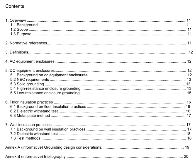
IEEE Std 1653.6 pdf download IEEE Recommended Practice for Grounding of DC Equipment Enclosures in Traction Power Distribution Facilities
5.2 NEC requirements
ln accordance with NEC Article 90.2(B)(1),installation for railways for generation,transformation,transmission, and distribution of power used exclusively for the operation of rolling stock are not coveredby the NECR[B4].5
5.3 Solid grounding
Solidly grounded dc enclosures are connected to earth ground through the bonding of neighboringequipment, building structure,and grounded electrodes with no intentional impedances installed betweenthe enclosure and ground.
The operation of solidly grounded equipment relies on the presence of very low-impedance connectionsbetween equipment enclosures and ground in order to minimize voltage potentials during normal operationand during fault conditions.
Due to the low operating voltage and correspondingly high operating current, particular attention must bepaid to providing an adequate earthing system and bonding conductor size. Insufficiently sized conductorsmay simply fuse (open circuit) and allow the affected equipment enclosure to elevate to the system voltage.An earthing system that exhibits excessive resistance may raise an entire building to the system voltage. Ifthe fault is remote from the supply, as is often the case in transit systems, conductor resistance may limitcurrents below feeder breaker trip settings and the fault may continue indefinitely.
An enclosure fault to railway negative may go almost totally unnoticed.Over time, the fault may causeearthing electrodes to be rendered ineffective by stray current corrosion. A negative fault may also causeenough current to flow to ground such that equipment bonds melt unnoticed and inadvertently isolate theequipment from safety grounds.
As a result, it is generally not recommended to solidly ground positive polarity dc equipment enclosuresdue to the high-energy nature of dc faults and the fact that some ground faults can be low in magnitude andnot detectable by overcurrent protective devices.
Freestanding negative polarity equipment enclosures and negative bus duct enclosures may or may not begrounded.
5.4 High-resistance enclosure grounding
5.4.1 Background on high-resistance enclosure grounding
High-resistance grounding is performed by isolating dc equipment enclosures from ground through the useof insulation and connecting the equipment chassis to ground through a high-resistance protective relaydevice.This is shown in Figure 1.
Protective relays function by applying a small dc voltage on the structure at all times and continuouslymonitoring the voltage on the enclosure. In the event that the measured voltage rises above its high-voltagetrigger during a hot structure fault or diminishes below the low-voltage trigger during a grounded structurefault,the 64 device initiates output signals in accordance with protective schemes implemented for thedevice.
High-resistance grounding was developed when the industry recognized that injury to personnel anddamage to equipment due to faults could be minimized by not grounding dc enclosures. Since fault currentsin high-resistance grounded enclosures are limited to below 1 A or less during a positive-to-enclosure fault,there is little to no damage to wiring, components, or equipment. Repairs can be made at very little cost,and equipment can be quickly restored to service once the fault condition has been removed. However, thepotentially high voltages necessitated the development of methods to protect personnel by designingequipment that could tolerate being energized to full system voltage during an enclosure fault. Thesemethods also included the development of relay schemes that could detect an energized structure as well asunintentionally grounded structures in the event of a fault.Refer to 5.4.2 for recommended protectionschemes.
As with any grounding design and installation, special care must be taken when high-resistance groundingis used as the insulation may be subjected to rated voltage. An accidental bridging of the insulation, due tometallic artifacts such as metal debris, is capable of bypassing the protective circuit.
5.4.2 Protection
Protection practices for high-resistance grounding depend primarily on the operating procedures of a transitagency, Some agencies may decide to only monitor hot or grounded structure fauilts and trigger an alarm.others may decide to trip traction power ac and dc breakers upon a hot structure fault event. Regardless ofthe protection scheme, the protective device should feature outputs that indicate when a hot or groundedstructure fault occurs. These outputs should then be used to employ the preferred protection scheme of theagency.
The recommended protection scheme for high-resistance grounding is to trip the ac breaker feeding therectifier transformer, dc cathode breaker, and dc feeder breakers upon a hot structure fault. Some systemsalso employ transfer tripping of dc breakers located at adjacent substations because of the possibility thatan enclosure fault may be fed from the load side of a local feeder breaker. For grounded structure faults, analarm should be annunciated to a local alarm panel at minimum. Protective relaying should be applied to
