ISO 7626 pdf download
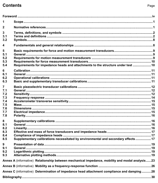
ISO 7626 pdf download Mechanical vibration and shock — Experimental determination of mechanical mobility — Part 1: Basic terms and definitions, and transducer specifications
For most practical applications, it is not necessary to know the entire 6N× 6N matrx. Often, it is sufficient tomeasure the driving-point mobility and a few transfer mobilities by exciting with a force at a single point in asingle direction and measuring the translational response motions at key points on the structure. In otherapplications, only rotational mobilities may be of interest.
Since mechanical mobility is defined as the frequency-response function formed by the ratio of the phasor ofthe translational or rotational response velocity to the phasor of the applied force or moment excitation, whenmeasuring with an accelerometer,conversion to velocity is required to obtain the mobility.Alternatively,accelerance,the ratio of acceleration to force,may be used to characterize a structure. in other cases,dynamic compliance, the ratio of displacement to force, may be used.
NOTE Historically, frequency-response functions of structures have often been expressed in terms of the reciprocalof one of the above-named dynamic characteristics. The arithmetic reciprocal of mechanical motility has often been calledmechanical impedance.This is misleading because the arithmetic reciprocal of mobiity does not,in general,representany of the elements of the impedance matrix of a structure. This point is elaborated upon in AnnexA.
Mobility test data cannot be used directly as part of an impedance model of the structure. In order to achievecompatibility of the data and the model, the impedance matrix of the model shall be converted to mobility orvice ‘versa (see A.3 for limitations).
Before carrying out mobility measurements, it is necessary to evaluate the characteristics of the force andmotion response transducers to be used in order to ensure that accurate amplitude and phase information canbe obtained over the entire frequency range of interest.
5 Basic requirements for force and motion measurement transducers
5.1General
The basic characteristics of all measurement transducers which are important in acquiring adequate mobilitydata are as follows.
a)Transducers shall have sufficient sensitivity and low noise in order to obtain a signal-to-noise ratio of the measurement chain which is adequate to cover the dynamic range of the mobility of the structure. Sincelightly damped structures require a larger dynamic range than structures with considerable damping,transducer noise is of particular concern when testing lightly damped structures.
b) lf the frequency-response function of the measurement transducer is not compensated by suitable signal processing, the natural frequency of the transducer shall be far enough below or above the frequencyrange of interest that no unacceptable phase shift occurs.
c)Transducer sensitivity shall be stable with time and have negligible direct current drift.
d) Transducers shall be insensitive to extraneous environmental effects,such as temperature,humidity,magnetic fields, electrical fields, acoustical fields,strain and cross-axis inputs.
e) Transducer mass and rotational inertia shall be small so as to avoid dynamic loading of the structure under test, or at least small enough so that a correction can be made for the loading.
Low susceptibility of the measurement system to the effects of electrical ground loops and other extraneoussignals is also important.
5.2Requirements for motion measurement transducers
5.2.1 Although motion measurement transducers require the characteristics outlined in 5.1, certain of thesecharacteristicsRare more important than others. Motion transducers used in mechanical mobilitymeasurements are most commonly accelerometers; however,displacement or velocity transducers aresometimes used.The major characteristics to be considered in transducer selection are outlined in 5.2.2 to5.2.5.
5.2.2 The motion transducer should be of low mass (or non-contacting) design so as to minimize structural loading of the structure under test.
5.2.3 The attachment of the transducer to the structure under test should be stiff in the direction of the primary measurement axis of the transducer (see ISO 5348 [2] ).
5.2.4 The attachment should have a sufficiently small contact area to prevent stiffening or damping of the structure by the transducer or its mounting fixture.
5.2.5 When applying impulse excitation, zero drift of piezoelectric accelerometers due to the pyro-electric effect is likely to occur and this limits the accuracy of the measurement at low frequencies. Other types of motion transducers (e.g. piezoresistive, electrodynamic or some shear-type piezo-electronic accelerometers) can provide the solution to this problem.
