ISO 16889 pdf download
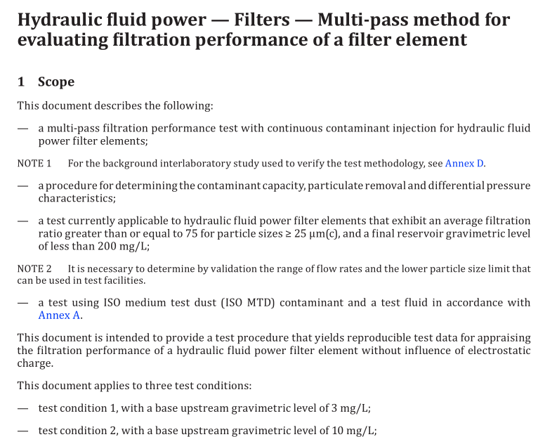
ISO 16889 pdf download Hydraulic fluid power — Filters — Multi-pass method for evaluating filtration performance of a filter element
1 scope
This document describes the following:
– a multi-pass filtration performance test with continuous contaminant injection for hydraulic fluid
power filter elements;
NOTE 1 For the background interlaboratory study used to verify the test methodology, see Annex D.
– a procedure for determiningthe contaminant capacity,particulate removalanddifferential pressure
characteristics;
a test currently applicable to hydraulic fluid power filter elements that exhibit an average filtrationratio greater than or equal to 75 for particle sizes ≥ 25 um(c), and a final reservoir gravimetric levelof less than 200 mg/L;
NOTE2 lt is necessary to determine by validation the range of flow rates and the lower particle size limit thatcan be used in test facilities.
-a test using lS0 medium test dust (ISO MTD) contaminant and a test fluid in accordance with
Annex A.
This document is intended to provide a test procedure that yields reproducible test data for appraisingthe filtration performance of a hydraulic fluid power filter element without influence of electrostaticcharge.
This document applies to three test conditions:
– test condition 1, with a base upstream gravimetric level of 3 mg/L;- test condition 2, with a base upstream gravimetric level of 10 mg/L;- test condition 3, with a base upstream gravimetric level of 15 mg/L.2Normative references
The following documents are referred to in the text in such a way that some or all of their contentconstitutes requirements of this document. For dated references, only the edition cited applies.Forundated references, the latest edition of the referenced document (including any amendments) applies.ISO 1219-1, Fluid power systems and components —Graphical symbols and circuit diagrams — Part 1:Graphical symbols for conventional use and data-processing applications
ISO 2942,Hydraulic fluid power—Filter elements—Verification of fabrication integrity and determinationof the first bubble point
ISo3722,Hydraulic fluid power —Fluid sample containers —Qualifying and controlling cleaning methodsISo 3968,Hydraulic fluid power —Filters — Evaluation of differential pressure versus flow
ISO 4021,Hydraulic fluid power —Particulate contamination analysis —Extraction of fluid samples fromlines of an operating system
IS04405,Hydraulic fluid power — Fluid contamination —Determination of particulate contamination bythe gravimetric method
ISO 5598,Fluid power systems and components – Vocabulary
IS0 11171,Hydraulic fluid power — Calibration of automatic particle counters for liquids
ISo 11943:2021,Hydraulic fluid power — Online automatic particle-counting systems for liquids 一Methods of calibration and validation
ISO12103-1:2016,Road vehicles —Test contaminants for filter evaluation —Part 1: Arizona test dust
3Terms and definitions
For the purposes of this document, the terms and definitions given in lSo 5598 and the following apply.ISO and IEC maintain terminology databases for use in standardization at the following addresses:- ISo online browsing platform: available at https://www.iso.org/obp
—IEC Electropedia: available at https://www.electropedia.org/
3.1General terms
3.1.1
contaminant mass injected
mass of specific particulate contaminant injected into the test circuit to obtain the terminaldifferentialpressure
3.1.2
rest conductivity
electrical conductivity at the initial instant of current measurement after a d.c. voltage is impressedbetween electrodes
Note 1 to entry: It is the reciprocal of the resistance of uncharged fluid in the absence of ionic depletion orpolarization.
3.1.3
retained capacity
mass of the specific particulate contaminant effectively retained by the filter element when the terminalelement differential pressure is reached
3.2Terms related to differential pressure3.2.1
differential pressure
difference between the tested component inlet and outlet pressure as measured under the specifiedconditions
Note 1 to entry:See Figure 1 for a graphical depiction of differential pressure terms.
3.2.2
clean assembly differential pressure
difference between the tested component inlet and outlet pressures as measured with a clean filterhousing containing a clean filter element
