IEEE Std 2779 pdf download
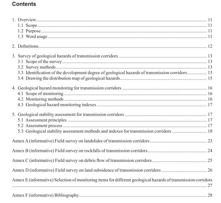
IEEE Std 2779 pdf download IEEE Guide for Assessment of Geological Stability of Transmission Corridors
4. Geological hazard monitoring for transmission corridors
4.1 Scope of monitoring The monitoring scope covers the transmission corridor and the area that may endanger secure operation of transmission lines. Monitoring objects mainly include landslides and rockfalls of transmission towers, debris- flow-prone gullies around towers and substation sites with a high probability of land subsidence. Monitoring scope can be expanded according to actual needs once wide-area monitoring methods, e.g., satellite remote sensing, are adopted.
4.2 Monitoring methods Monitoring methods include various technical means such as manual patrol, online monitoring, satellite-based remote sensing monitoring, UAV-mounted small-size laser radar (LiDAR) patrol. See Annex E for monitoring items for geological hazard deformation.
a) Manual patrol: As for accessible areas, crack water level of debris fow channel and land subsidence amount can be manually measured with tapes or other simple instruments at regular intervals, so as to observe the trends and record the variation.
b) Online monitoring: On-site image monitoring, rainfall monitoring, and geohazard deformation monitoring methods based on optical fber sensing technology, electronic sensing technology, IOT technology, and satellite positioning technology are recommended. The development of monitoring devices involves key technologies such as perception and collection of hazard information, operating supplies of monitoring devices, and data transmission and communications. Sensor measurement accuracy should meet the measurement needs of the infuencing factors of geological hazards. If monitoring devices operate outdoors, operating supplies can be solar energy or batteries. Communications of monitoring data can be implemented by public data networks, wireless private networks of the power grid, or special optical fber lines.
c) Satellite-based remote sensing monitoring: Aerial photography remote sensing (high-resolution superior to 1.0 m) and interferometric synthetic aperture radar (InSAR) can be adopted to perform quantitative monitoring for deformation of geological hazards. Open satellite data source and paid data source can be adopted as the remote sensing data source. As for major monitoring objects, long- time-series tracking monitoring may be adopted to monitor geological hazards, target facilities, displacement and settlement and other factors. Atmospheric interferences and time delays can be eliminated during data processing and the submitted data can meet practical engineering needs.
d) UAV-mounted LiDAR monitoring: Small-size UAV-mounted laser radar (LiDAR) is recommended for patrol to survey ground deformation of transmission corridors and record the development state of hazards. For the surface covered by vegetation, vegetation can be fltered by means of data processing based on the penetration performance of LiDAR signals on vegetation to restore the topography under the vegetation, thereby observing and identifying hazard status in a better way.
4.3 Geological hazard monitoring indexes Requirements for tower tilting: Equipment should be handled once it operates beyond the following criteria or has the following conditions that should not appear: the tilt monitoring alarm value should be measured under the condition of no ice and under wind speed of 5 m/s and annual average temperature, and the tilting level of towers that are above 50 m shall not exceed 0.5% of the whole height of the tower, and for towers below 50 m, the tilting level shall not exceed 1.0% of the tower height. Requirements for landslides: Monitoring accuracy resolution can be selected as 1 mm for displacement and crack monitoring; monitoring accuracy resolution can be selected as 0.1% for moisture content monitoring. Resolution of other monitoring items can refer to the requirements of other hazards. Requirements for rockfalls: For monitoring dip angle and accelerated speed, monitoring accuracy resolution can be selected as 0.1 degree and 1 mm, respectively. Resolution of other monitoring items can refer to the requirements of other hazards. Requirements for debris fow: Monitoring accuracy resolution of 1 mm/min and 1 cm can be adopted for monitoring rainfall and mud level. Requirements for land subsidence: Monitoring accuracy resolution of 1 cm and 1 mm can be adopted for monitoring underground water and subsidence.
5. Geological stability assessment for transmission corridors
5.1 Assessment principles After the formation conditions, distribution types, movement range, deformation characteristics, inducing factors, and formation mechanism of various geological hazards that have occurred (or are potential) in the assessment zone and surrounding areas are basically found out, existing remote sensing images, data on regional geology, hydrogeology, engineering geology, and environmental geology can be further collected and used for evaluating the geological stability of transmission corridors. If necessary, geophysical prospecting, pit prospecting, drilling, or sampling test can be carried out. The geological stability assessment results of transmission corridors shall be in accordance with the national and local regulations. 5.2 Assessment process The assessment is as follows:
