IEC 60445 pdf – Basic and safety principles for man-machine interface, marking and identification – Identification of equipment terminals, conductor terminations and conductors
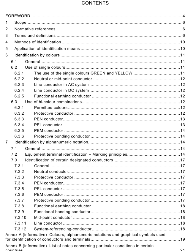
IEC 60445 pdf – Basic and safety principles for man-machine interface, marking and identification – Identification of equipment terminals, conductor terminations and conductors
A neutral or mid-point conductor shall be identified by the colour BLUE. In order to avoidconfusion with other colours it is recommended to use an unsaturated colour BLUE, often called”light blue”.
Where a neutral or mid-point conductor is present,the colour BLUE shall not be used foridentifying any other conductor. In the absence of a neutral or mid-point conductor within thewhole wiring system, the colour BLUE may be used for identifying a conductor with any otherpurpose, except as a protective conductor.
Bare conductors used as neutral or mid-point conductors shall be either coloured by a BLUEstripe,15 mm to 100 mm wide in each unit or enclosure and at each accessible position, orcoloured BLUEthroughout their length.
NOTE ln IEC 60079-11, the colour BLUE is used for the marking by colour of terminals,terminal boxes,plugs andsockets of intrinsically-safe circuits.
6.2.3 Line conductor in AC system
Line conductors in AC systems shall be identified by the colours BLACK,BROWN or GREY.
NOTE The sequence of colour codes in 6.2.3 is in alphabetical order in the English language, and does not indicateany preferred phasing or direction of rotation.
6.2.4 Line conductor in Dc system
Line conductors in DC systems shall be identified by the colour:-RED for the positive line conductor,
– WHITE for the negative line conductor.6.2.5 Functional earthing conductor
Afunctional earthing conductor shall be identified by the colour PINK. lt is only necessary toapply the identification at the terminations and at points of connection.
6.3Use of bi-colour combinations
6.3.1 Permitted colours
Any two of the colours listed in 6.1 may be combined, provided there is no risk of confusion.
To avoid any such confusion, the colour GREEN and the colour YELLOW shall not be used incolour combinations other than the combination GREEN-AND-YELLow.
The colour combination GREEN-AND-YELLOW shall only be used for the purposes specified in6.3.2 to 6.3.6.
6.3.2Protective conductor
Theprotective conductor shall beidentified by the bi-colour combinationGREEN-AND-YELLow.
GREEN-AND-YELLOW is the only colour combination recognized for identifying the protectiveconductor.
For a PEN,PEM,and PEL conductor, additional requirements are given in 6.3.3 to 6.3.5.
The colour combination GREEN-AND-YELLOW shall be such that, on any 15 mm length of theconductor where colour coding is applied, one of these colours covers at least 30 % and notmore than 70 % of the surface of the conductor, the other colour covering the remainder of thatsurface.
lf bare conductors used as protective conductors are provided with colouring they shall becoloured GREEN-AND-YELLow, either throughout the whole length of each conductor or ineach compartment or unit or at each accessible position. lf adhesive tape is used,onlybi-coloured GREEN-AND-YELLOW tape shall be applied.
Where the protective conductor can be easily identified by its shape, construction or position,for example a concentric conductor,colour coding throughout its length is not necessary butthe ends or accessible positions should be clearly identified by the graphical symbol lEC 60417-5019 (2006-08)”Protective earth; protective ground”,(), or the bi-colour combinationGREEN-AND-YELLow or the alphanumeric notation PE.
lf extraneous conductive parts are used as a protective conductor, identification by colours isnot necessary.
6.3.3 PEN conductor
A PEN conductor, when insulated, shall be identified by one of the following methods:
– GREEN-AND-YELLow coloured insulation throughout its length and with BLUE colourmarkings at the terminations and points of connection; or
BLUE coloured insulation throughout its length and with GREEN-AND-YELLOw colouredmarkings at the terminations and points of connection.
The method to be applied within a country should be decided by the National Committee andnot on an individual basis.
The BLUE coloured markings at the termination and points of connection may be omittedprovided one of the following two conditions is met:
– in electrical equipment, if relevant requirements are included in specific product standards
or within a country;
in the case of wiring systems, for example those used in industry, if decided by the relevantcommittee.
6.3.4PEL conductor
A PEL conductor,when insulated, shall be identified by GREEN-AND-YELLOW colouredinsulation throughout its length and with BLUE coloured markings at its terminations and pointsof connection of the PEL conductor.
