BS EN ISO 20312 pdf download
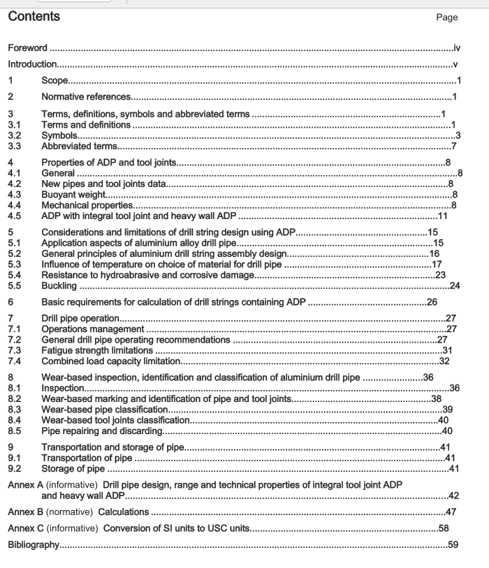
BS EN ISO 20312 pdf download Petroleum and natural gas industries — Design and operating limits of drill strings with aluminium alloy components (ISO 20312:2011)
1 Scope
This International Standard applies to design and operating limits for drill strings containing aluminium alloypipes manufactured in accordance with ISO 15546.
2Normative references
The following referenced documents are indispensable for the application of this document. For datedreferences,only the edition cited applies.For undated references, the latest edition of the referenceddocument (including any amendments) applies.
IsO 9712,Non-destructive testing — Qualification and certification of personnelISO 15546,Petroleum and natural gas industries —Aluminium alloy drill pipe
ASNT Recommended Practice No.SNT-TC-1A, Personnel Qualification and Certification in Non-destructiveTesting
3Terms, definitions, symbols and abbreviated terms3.1Terms and definitions
For the purposes of this document, the following terms and definitions apply.3.1.1
aluminium alloy pipe body
aluminium alloy pipe formed by extrusion, including upsets and protector thickening
3.1.2
aluminium alloy drill pipe
aluminium alloy pipe body with threaded steel tool joints
3.1.3
box
tool joint part that has internal tool-joint thread
3.1.4
buckling
unstable lateral deflection of a drill stem component under compressive effective axial force
3.1.5
corrosion
adverse chemical alteration or destruction of a metal by air, moisture or chemicals
3.1.6
critical buckling load
lload level associated with initiation of drill stem components buckling
3.1.7
dogleg
sharp change of direction in a well bore3.1.8
dogleg severity
measure of the amount of change in the inclination and/or direction of a borehole,usually expressed indegrees per 30 m interval
3.1.9
drill string
complete assembly from the swivel or top drive to the drill bit, which can contain the kelly, drill pipes, subs, drllcollars and other bottom hole assembly (BHA) members, such as stabilizers, reamers and junk baskets
3.1.10
effective axial force
force created by adverse combinations of axial load and pressure
3.1.11
helical buckling
buckling in which drill stem components form a helix or spiral shape
3.1.12
manufacturer
firm, company or corporation responsible for marking the product
NOTE Marking by the manufacturer warrants that the product conforms to this International Standard,and it is themanufacturer who is responsible for compliance with all of its applicable provisions.
3.1.13
new class pipe
wear-based classification of pipe not having been put in service
3.1.14
pin
tool joint part that has external tool-joint thread
3.1.15
premium class, class 2 pipe
wear-based classification of pipe worn to an extent listed in Tables 12 and 13
3.1.16
sinusoidal buckling
buckling of drill stem components in a sinusoidal shape3.1.17
slip area
area within a small distance along the pipe body from the box end, clamped by the pipe slips during the pullingand running operations
3.1.18
tool joint
steel tool joint element for drill pipes consisting of two parts (pin and box)
3.1.19
TT type thread
trapezoidal-shaped thread connecting aluminium pipe body and steel joint
NOTE See ISO 15546.
3.2 Symbols
A factor depending on the failure theory selected for calculations and adjusted for anisotropy of drill pipe
material
A b box cross-sectional area at 9,525 mm from the bearing face
A dp drill pipe cross-sectional area
A OD cross-sectional area circumscribed by pipe outside diameter
A p pin cross-sectional area at 15,875 mm from the bearing face
A pb cross-sectional area of pin A p or box A b , whichever is smaller
A z cross-sectional area of drill pipe in upset part
a e coefficient of linear expansion of material
a w cross-sectional area of pipe wall with regard to pipe ovality
B variable
b strain reduction factor
C pitch diameter of thread at gauge point
c area coverage coefficient
D dp pipe body outside diameter
D h average diameter of the borehole at the regarded interval
D max maximum outside diameter of pipe
D min minimum outside diameter
D pt protector outside diameter
D tj tool joint outside diameter
D U outside diameter of drill pipe in upset part
D conventional outside diameter of drilling pipe with tool joint
d dp pipe body inside diameter
d p pin inside diameter
