AS NZS 3629.11 pdf download – Methods of testing child restraints Method 11: Measuring energy attenuation
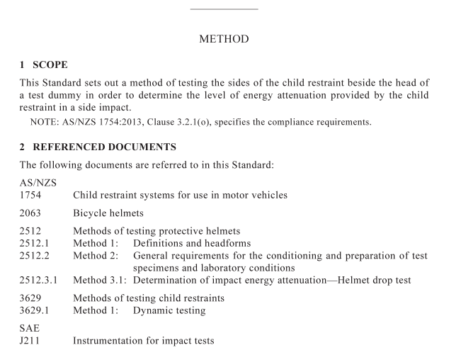
AS NZS 3629.11 pdf download – Methods of testing child restraints Method 11: Measuring energy attenuation
3 DEFINITIONS For the purpose of this Standard, the definitions given in AS/NZS 2512.1 and AS/NZS 1754 apply.
4 PRINCIPLE A sectioned head restraint/side wing from a child restraint is positioned on the surface and an appropriate instrumented headform is dropped in guided free fall. The acceleration imparted to the assembly is measured.
5 APPARATUS The following test apparatus is required:
(a) Headform of the dimensions and design specified in AS/NZS 2512.1:2009 as ‘Headform A’, made of Mg K1A material and instrumented as described in Item (d)(iv) below. NOTE: A material with the following composition has been found suitable— magnesium/zirconium binary alloy with 0.3% to 0.8% zirconium, d = 1.79 ±0.01 kg/dm 3 .
(b) An anvil consisting of a solid mass of at least 450 kg faced with a steel plate of at least 25 mm in thickness and having a lateral dimension of at least 500 mm × 500 mm.
(c) Release mechanism capable of smoothly releasing the drop assembly.
(d) A drop assembly complying with the following:
(i) It shall consist of a headform (size A) and a supporting assembly, the combined mass of which shall be 3.1 ±0.05 kg.
(ii) The mass of the supporting assembly, which comprises the supporting arm and ball socket stem, shall not exceed 20% of the mass of the drop assembly. NOTE: It may be necessary to obtain the mass of the ball socket stem by calculation.
(iii) The centre of mass of the combined test headform and supporting assembly shall be within a cone with its axis vertical and forming a 10° included angle with the vertex located at the point on the external surface of the test headform, which is vertically below the centre of the accelerometer. (See Figure 1). The combined centre of mass shall be determined for all points on the headform above the test line.
NOTES: 1 This is because, as the headform rotates, the combined centre of mass changes. 2 This may be accomplished mathematically once the centre of mass of the headform and support assembly has been determined.
(iv) An acceleration transducer shall be mounted at the centre of the ball socket, with the sensitive axis aligned to within 5° of the vertical when the test headform is in the impact position.
(v) The acceleration data channel shall comply with the requirements for Channel Class 1000 of SAE J211.
(vi) A means to control the direction of the free fall.
(e) Means of securing the child restraint test specimen to hold it in position prior to, and whilst, the headform is impacting the specimen.
(f) Apparatus as specified in AS/NZS 3629.1 required for testing the child restraint in side impact. Typical apparatus for impact energy attenuation test is shown in Figure 2.
6 VERIFICATION OF TEST APPARATUS The velocity of impact shall not differ by more than 3% from the velocity of impact theoretically obtainable in free fall in vacuum, within 50 mm of the point of impact from the specified drop height.
NOTE: Increasing the drop height above the tolerance specified in the product Standard is not acceptable.
7 TEST SPECIMEN The following apply:
(a) The test specimen shall not have been previously tested and sampled from a production batch.
(b) The child restraint shall be sectioned ensuring to maintain the structural integrity of the head restraint or side wing within the region of the test site, in accordance with Clause 8(b)(iv). 8 PROCEDURE This test method is based on testing helmets as the helmet test methods may assist in conducting this test procedure. The procedure shall be as follows: (a) Determination of test sites:
(i) Position the child restraint on the test seat as specified in Clause 7(a) of AS/NZS 3629.1:2013 and shown in Figure 1 of AS/NZS 3629.1:2013. (ii) Select the largest appropriate test dummy, specified in the requirements of AS/NZS 1754:2013, Table 5.1, Sideways with door, for dynamic testing. Record the test dummy selected. (iii) Install the child restraint on the test seat, as specified in the manufacturer’s instructions, and correctly position the appropriate test dummy into the restraint.
