AS ISO 22915.11 pdf download – Industrial trucks—Verification of stability Part 11: Industrial variable-reach trucks
AS ISO 22915.11 pdf download – Industrial trucks—Verification of stability Part 11: Industrial variable-reach trucks
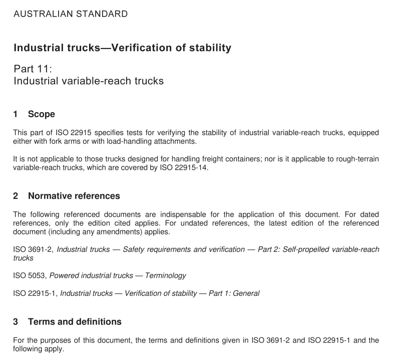
1 Scope
This part of lSO 22915 specifies tests for verifying the stability of industrial variable-reach trucks, equippedeither with fork arms or with load-handling attachments.
lt is not applicable to those trucks designed for handling freight containers; nor is it applicable to rough-terrainvariable-reach trucks, which are covered by lso 22915-14.
2Normative references
The following referenced documents are indispensable for the application of this document.For datedreferences,only the edition cited applies. For undated references, the latest edition of the referenceddocument (including any amendments) applies.
ISO 3691-2,Industrial trucks — Safety requirements and verification — Part 2:Self-propelled variable-reachtrucks
ISO 5053,Powered industrial trucks — Terminology
IsO 22915-1,Industrial trucks — Verification of stability —Part 1 : General
3Terms and definitions
For the purposes of this document, the terms and definitions given in ISO 3691-2 and IS0 22915-1 and thefollowing apply.
3.1
variable-reach truck
counterbalanced lift truck with an articulating boom, telescopic or not, non-slewing as defined in IlSO 5053 orhaving a slewing movement of not more than 5° on either side of the truck’s longitudinal axis,used forstacking loads
NOTE1 The load-handling means may be mounted directly on the liting means or on an auxiliary mast fixed at theend of the lifting means.
NOTE2 Variable-reach trucks may be fitted with a rigid or articulating chassis, stabilizers, axle-locking or lateral framelevelling devices as defined in ISO 3691-2, or two- or four-wheel steering or articulating chassis steering systems.
3.2
industrial variable-reach truck
variable-reach truck designed for operation on substantially firm, smooth, level, prepared and consolidatedsurfaces
4 Test conditions
4.1 General
See ISO 2291 5-1 .
4.2 Position of truck on the tilt table
4.2.1 Load and steer axles
The load/drive axle and the steer axle are defined by Figure 1 .
4.2.2Tests 1 and 2
The truck shall be positioned on the tilt table so that its load axle, C-C, and steer axle,B-B, are parallel to thetilt axis,x-Y, of the tilt table.See Table 1.
4.2.3 Tests 3,4 and 5
The truck shall be positioned on the tlt table in a turning position with the line,M-N, parallel to the tilt axis,X-Y, of the tilt table. See Table 1.
For trucks with an articulating steer axle, the wheel on the steer axle nearest to the tilt axis,X-Y, shall beparallel to X-Y.See Table 1.
Point M is defined as follows:
a) For trucks with an articulating steer axle: point M shall be the projection onto the tlt table of the intersection of the longitudinal centre plane,A-A, of the truck with the axis of the steer axle (see Table 1).
b) For trucks with an articulating chassis: point M shall be the projection onto the tlt table of the intersection of the longitudinal centre plane,J-J, of the rear chassis’ module and the axis of the rear axle (seeTable 1) when fully articulated.
c) For trucks with axle locking: point M shall be the centre point of the area of contact between the tilt table and the rear wheel nearest to the tilt axis, X–Y, of the tilt table (see Table 1 ). As shown in Table 1 , point N is defined as the centre point of the area of contact between the tilt table surface and the load wheel (or stabilizer pad, if fitted) closest to the tilt axis, X–Y, of the tilt table.
4.3 Test load Tests 1 and 3 shall be conducted with the test load in the least stable combination of lift and reach, with the fork arms in the horizontal position. Test 5 shall be conducted at maximum and minimum boom extensions, at the maximum boom angle and with the fork arms in the horizontal position. See Table 1 .
4.4 Lift height For tests simulating travel, i.e. Tests 2 and 4, the upper face of the fork arms, measured at the heel of the fork arm when fully tilted rearward, shall be positioned
