AS 6401 pdf download – Knife-gate valves for waterworks purposes
AS 6401 pdf download – Knife-gate valves for waterworks purposes
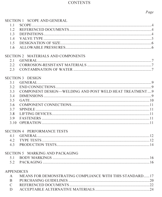
1.1 sCOPE
This Standard specifies requirements for Class 10 flanged,wafer and lugged,rising andnon-rising spindle,uni-directional and bi-directional,gland box and bonneted knifc-gatevalves of sizes DN 50 to DN 15o0 inclusive for:
(a)cold potable water supply (up to 40°C); and
(b)drainage and sewerage systems (continuous flow up to 45°C and intermittent flow up
to 95°C).
The valves are designed for operation by manual hand wheel cither above ground or buriedor submerged with an extension spindle.
Means for demonstrating compliance with this Standard are given in Appendix A.NOTES:
l Purchasing guidelines are given in Appendix B.
2The design of the extension spindle is not covered in this Standard.
1.2REFERENCED DOCUMENTS
The documents referred to in this Standard are listed in Appendix C.1.3DEFINITIONS
For the purpose of this Standard,the definitions below apply.1.3.1 Knife-gate valve
A valve that provides on/off control by means of a thin, parallel sliding gate and guide.1.3.2 Allowable operating pressure
The allowable internal pressure, excluding surge, that a component can safely withstand inservice.
1.3.3 Maximum allowable operating pressure
The allowable internal pressure,including surge, that a component can safely withstand inservice.
1.3.4Allowable test pressure
The maximum internal hydrostatic pressure that can be applied on site to a component in anewly installed pipeline.
1.3.5 Bi-directional
The valve is designed to seal against the flow in either direction.
1.3.6Bulk head test
A test where the testing machine provides external restraint to make a watertight joint ateach end of the valve.
1.3.7Class
The allowable operating pressure of the valve expressed in hundreds of kilopascals.1.3.8 Coating
A corrosion-inhibiting medium applied to the surfaces of a valve.1.3.9 Coating defect
A detectable weakness or discontinuity in a coating which deems it to be suspect in itsability to protect the substrate from corrosion during its normal service life.
1.3.10 Distortion
Any permanent deformation.1.3.11 DN (Nominal size)
An alphanumeric designation of size for components of a pipework system,which is usedfor reference purposes. It comprises the letters DN followed by a dimensionless wholenumber that is indirectly related to the physical size, in millimetres,of the bore or outsidediameter of the end connections.
1.3.12 Face to face dimensions
The distance between the valve mating faces measured along the valve axis.1.3.13 Free end test
A test where the valve ends are blanked off so that the axial hydraulic force is notexternally restrained.This simulates a valve in a terminal position held rigidly at one endonly.
1.3.14 Non-rising spindle design
A valve design where the gate is attached to the spindle, such that as the gate moves fromclosed to open position the spindle does not rise during operation.
1.3.15 Rising spindle design
A valve design where the gate is fixed to the spindle such that as the gate moves fromclosed to open position the spindle rises during operation.
1.3.16Un-directional
The valve is designed to secal against the flow in one direction only1.3.17 Type test
A once only set of tests carried out to prove performance.1.4VALVE TYPE
Valves shall be of the wafer,flanged or lugged type for installation between flanges, or forinstallation at a termination point.
The valve may be supplied in any of the following configurations:(a) Rising or non-rising spindle.
(b) Uni-directional or bi-directional flow.
(c)Yoke and gland box or bonneted valve spindle support system.
