AS 4133.4.3.2 pdf download – Methods of testing rocks for engineering purposes Method 4.3.2: Rock strength tests— Determination of the deformability of rock materials in uniaxial compression—Rock strength less than 50 MPa
AS 4133.4.3.2 pdf download – Methods of testing rocks for engineering purposes Method 4.3.2: Rock strength tests— Determination of the deformability of rock materials in uniaxial compression—Rock strength less than 50 MPa
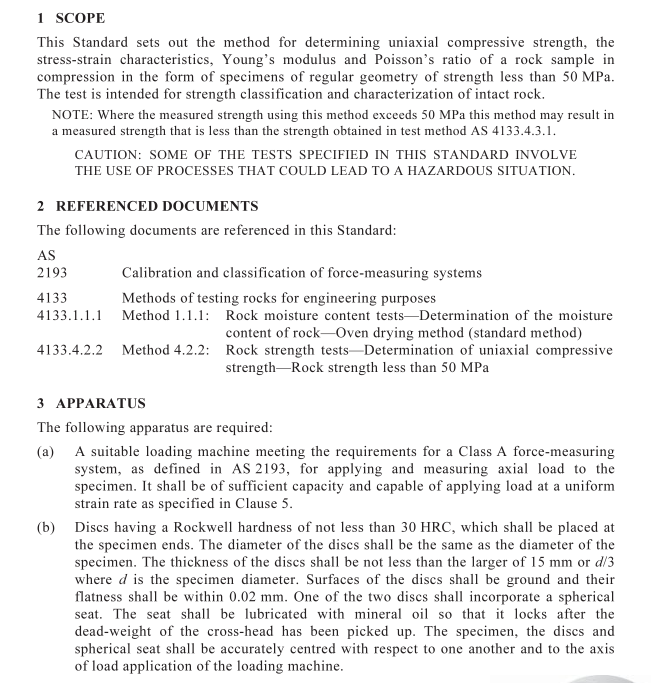
The centre of curvature of the spherical seat surface shall coincide with the centre ofthe specimen top face.
(c)A measuring instrument such as vernier or micrometer calipers capable of measuring
specimen dimensions to a precision of 0.1 mm.
(d) Electrical resistance strain gauges,extensometers,optical devices or other suitable
measuring devices. Their design shall be such that an average of two circumferentialand two axial strain measurements, equally spaced, with the position of the mid pointof the gauges or other devices located at the mid-point of the specimen anddiametrically opposite each other, can be determined for each increment of load,witha strain sensitivity of not less than 5 x 10⁻⁶.
NOTES:
1Whatever devices are selected,it is recommended that they are checked against the
known properties of specimens tested in a manner described in Clause 5. A suitablespecimen should consist of a right cylinder of aluminium or steel.Such procedures areessential when using devices other than electrical resistance strain gauges.
2Strain gauges should be bonded to the specimen by a suitable epoxy resin.
Where electrical resistance strain gauges are used, the length of the gauges overwhich axial strain is determined shall be at least 10 grain diameters in magnitude andthe gauges not encroach within d/2 of the specimen ends,where d is the diameter ofthe specimen. Circumferential strain shall be determined over a gauge length ofbetween 5% and 10% of the circumference of the specimen.
NOTE: Electrical resistance strain gauges should only be used for non-friable, coherent rock,which permit an effective bond between the rock surface and the strain gauge. Alternativetechniques are generally necessary for rocks that fall outside this category or for rocks whosemoisture content precludes the necessary bond between the gauges and the rock surface.
Where dial gauges or LDVTs are used, the dial gauges or LDVTs shall be readable toa minimum of 0.002 mm.
The gauges shall be centrally positioned with a gauge length of not less than d.(c)An apparatus for continuously recording load and deformation.
4PREPARATION OF TEST SPECIMEN
4.1Sampling
Prior to specimen preparation, samples should be stored in such a way as to preserve thenatural water content. The period of storage should preferably not exceed 30 days. It isrecognized that in some cases for some materials,e.g. shales,mudstone/claystones andlaminites,it may be desirable to test specimens in the ‘as received’moisture conditions.These materials may also deteriorate if stored for any length of time or where saturated.Such conditions should be noted in the test report. It is also recognized that in some casesfor some materials,it may be desirable to test specimens in a fully saturated condition. Ifthis is the casc,the test report should note this and report how the specimens weresaturated.
NOTE: See Appendix A for further information on the influence of moisture condition on rockstrength.
4.2Specimen preparation
The test specimen shall be prepared as follows:
(a) From a suitable sample prepare a test specimen having the following characteristics:
(i) Test specimen shall be a straight circular cylinder having a length to diameter
ratio of between 2.5 and 3.0 and a diameter preferably of not less than 45 mm.The diameter of the specimen shall be at least ten times the size of the largestgrain in the rock.
NOTE: While a test specimen length to diameter ratio in the range of 2.5 to 3.0 isspecified, in accordance with that recommended by ISRM, it is recognized that there isevidence suggesting that a minimum length to diameter ratio of 2.0 may be adequateparticularly for rocks with strength less than 25 MPa. Therefore,while a ratio ofbetween 2.5 to 3.0 is preferred, it is possible to extend this range to between 2.0 and3.0 to allow additional testing where the core lengths are limited. Where the ratio isless than 2.5, it should be noted in the test report.
(ii) The ends of the specimen shall be cut parallel to each other to within 1° and at
right angles to the sides of the specimen to within 1°.
(iii) The ends of the specimen shall be ground flat to 0.1 mm across the face with no
surface irregularities. If the ends of the specimen cannot be ground or containsurface irregularities they may be capped using a capping material that has astrength greater than 50 MPa.
(iv) The sides of the specimen shall be free of abrupt irregularities and straight over
the full length of the specimen.
(b)Determine the average original diameter of the specimen to at least the nearest
0.1 mm across two diameters at right angles and at the centre and near the top andbottom of the specimen. Calculate the average original diameter (d,) of the testspecimen from the six measurements.
(c)Measure and record the height of the specimen to 0.1 mm.(d)lf required,moisture condition the specimen prior to testing.
