API TR 2578 pdf download
API TR 2578 pdf download Flow Conditioner Installation and Effects on Turbine Meters
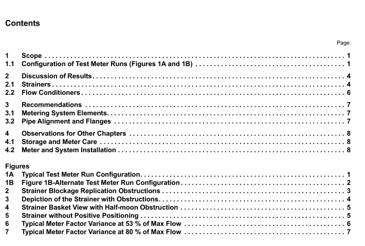
2.1.2 The data from our testing shows that the larger the strainer inletloutlet and body, the lower the variation inmeter factor (MF) on proving runs.
a) For the same nozzle size and configuration, a larger bodybasket yielded slightly less variance in MF on the
test runs.
b) For the same body size, a larger outlet nozzle size gave noticeably less variance in MF on the test runs.
c) The MF stability improves noticeably at strainer outlet nozzle velocities s 15 fps, and is greatly improved ≤ 10
fps.
d)Only conical or concentric reducers were used at the strainer nozzle outlet.
e)The strainer basket being secured/fixed inside the body reduces the varying perturbations that the basket
adds to the flow profile.
2.2Flow Conditioners
2.2.1 Flow conditioner installation location has a considerable effect on performance.Users should alwaysfollow the OEM installation recommendations.
2.2.2 Tube bundles provided erratic flow conditioning performance.Water testing first demonstrated that tubebundles exhibited unacceptable results based on meter factor stability (Figures 6 and 7).
2.2.3 Similar meter deviations when testing with tube bundles were observed on the initial Phase ll petroleumtests. Therefore, tube bundles were eliminated from all remaining petroleum testing that constituted the majority ofthe tests.
2.2.4 For all the remaining tests referenced in 2.2.3 (above), only high-performance flow conditioners wereused.
NOTE High-performance flow conditioners are defined as those that provide pseudo-fully developed flow in laboratory andfield piping configurations.
3Recommendations
ln all turbine meter applications,high-performance flow conditioners should be used to optimize meterperformance.
3.1 Metering System Elements
Strainer baskets should be as rigid as possible:
3.1.1 The strainer basket flange and perforated plate need to resist movement during operation.
3.1.2 Have a method to ensure exact placement in the strainer body when removed for cleaning andreplacement.
3.1.3 For custody transfer measurement systems with turbine meters, straight pipe of 20D alone (or, for thatmatter, any length) did not demonstrate acceptable performance to be considered flow conditioning.”
3.1.4 For custody transfer metering systems with turbine meters tube bundles did not demonstrate acceptableperformance and should not be considered high-performance flow conditioning.
3.1.5 Because position of the high-performance flow conditioner can affect the effectiveness,OEMrecommendations for location of the flow conditioner should be followed.
3.1.6Testing has indicated that additional APl flow conditioning testing for other non-positive displacementmeters should be considered.
3.2Pipe Alignment and Flanges
Correct-size gaskets,flange alignment,and pipe bore size should be used to ensure that there is noobstruction/restriction in the pipeline.
4Observations for Other Chapters4.1Storage and Meter Care
4.1.1 Users should always follow the manufacturer’s recommendations for the storage of spare turbine meters.NOTEDuring Phase ll (as well as Phase l) testing, when meters were removed from the piping and then reinserted severaldays or weeks later, the meter often took several hours of operation before becoming repeatable to the extent of the typical AdHoc data.
4.1.2Users should be aware that following periods of storage in atmospheric conditions, all fow meters requirea “break-in” period in the flowing stream to stabilize.
NOTE This “break-in” period could eliminate the need to prove the meter several times shortly after meter installation.4.1.3 lf no OEM instructions are provided, the meter should be cleaned upon removal.Storage with the shaftvertical and meter ends sealed is recommended.
4.2Meter and System Installation
4.2.1 Slip-on flanges are discouraged because of issues concerning bore alignment of the high-performanceflow conditioner or turbine meter alignment (steps, gaps,offsets). Butt-weld flanges with the bore machinedsmooth should be used.Socket-weld flanges may be acceptable.
4.2.2Users should always follow manufacturer’s recommendations for metering system equipment installation,operation, and maintenance.
