API TR 17TR15 pdf download
API TR 17TR15 pdf download API 17H Hydraulic Interfaces for Hot Stabs
4.3Types of Hot Stabs
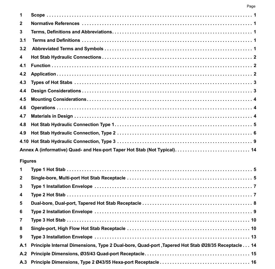
This technical report defines three categories of hot stabs.Each category is defined by profile (single bore or dualbore) and diameter. The described categories are intended for all future standard designs. These types supersedethe type A,B,C, and D described in the second edition of APl 17H.
Type 1: Single-bore Multi-port
Type 2: Dual-bore Multi-portType 3: Single-port High Flow
Type 1 and Type 2 hot stabs are typically used for making a temporary hydraulic or gas connection to a remote pieceof subsea equipment where high pressure/low flow applications are required.
Type 3 hot stabs utilize large bore connections intended for applications that require larger flow rates such as subseaBOP hydraulic control, flushing operations, and high flow circulation.
4.4Design Considerations
The geometry of the internal profile of the female receptacle is defined in this technical report. Design of the male stabis left open to interpretation to allow for variation in the selection of seal types, material, and fabrication tolerances.
All dimensions are interface dimensions and assume no coatings have been applied. If coatings are utilized, theinterface dimensions given shall be measured after coating is applied.
lsolation valves (needle valve or ball valve) may be used on hydraulic ports to reduce water ingress/contaminationinto fluid and to reduce leakagelspill to environment.
Test port applications commonly use isolation valves to provide a hydraulic lock on the hydraulic circuit and preventseawater ingress.
The hot stab should feature a flexible or compliant section between the handle and the stab body to assistmanipulator access during insertion or retrieval.
The hot stab should be equipped with a guide nose to ensure first stage alignment of stab into receptacle duringconnection.
The hydraulic interface between the receptacle and subsea piping/tubing shall be an industry standard such asthreaded Medium Pressure (MP)High Pressure (HP)BSP/SAE/NPT,APl 17SS or 6BX flange.
Locking male hot stabs should fit into all locking and non-locking female receptacles to ensure backward compatibility.
High flow (locking) receptacles shall be compatible with high flow locking and non-locking male stabs.
Correct and full mating between male stab and female receptacle should be clearly visible using a standard ROvmounted subsea camera. The interface between the male stab and female receptacle should use contrasting colorsas an aid.
Seal areas in female receptacles have been specified such that the male hot stabs can be produced with a variety ofseal designs.
lf plastic components are selected for use on the male ROV hot stab, the designer shall consider the short- and long-term effects of seawater exposure,including potential dimensional changes and swelling of plastics caused byabsorption of seawater that may prevent the hot stab from being extracted from the receptacie.
The required stab force should be kept as low as possible. The required stab force should be verified anddocumented by the hot stab manufacturer.
Hot stab applications utilizing unsecured hoses can introduce separation forces into the system.In these applications,it is recommended to include a mechanical locking feature that will retain the male hot stab and prevent separationfrom the female receptacle.
4.5Mounting Considerations
Sufficient space shall be provided around the female receptacle to ensure full engagement of the male stab and forthe removal of any debris from the receptacle. The recommended envelopes are shown in the figures and drawings.The hot stab female receptacle should be mounted in the horizontal plane where possible to prevent debris fromcollecting in the receptacle.
A pressure-retaining blanking (or dummy) male stab is recommended to be inserted into the female receptaclesubsea when the hot stab is not being utilized, unless using a pressure-retaining blanking (or dummy) male stab willbe detrimental to equipment or application. The blanking (or dummy) male stab provides seal surface protection fromcalcification, debris, and marine growth, as well as acting as a secondary barrier to the hydraulic system.A non-pressure-retaining blanking (or dummy) male stab can also be utilized, but will not act a secondary barrier to thehydraulic system.
Where blanking (or dummy) male stabs are used, a parking slot can be provided for parking the blanking (or dummy)hot stab. Lanyards can be used to attach blanking (or dummy) hot stabs to subsea equipment to prevent loss whenremoved. lt is important that lanyards are of sufficient length that they do not inhibit ROV manipulator operation.
When installing the hot stab receptacles onto ROV interface panels, the face of the female receptacle should beprotruding above the outer surface of the ROV panel. lf the receptacle is mounted to the inner surface of the ROvinterface panel, the panel should be no greater than 0.75 in.(20 mm) thick with a free access area large enough toaccommodate the male hot stab including the associated hydraulic fittings.
lf the mounting flange on the receptacle utilizes a split flange design, then it should utilize an ant-rotation feature toprevent the receptacle from rotating.
4.6Operations
Hot stabs may be operated by manipulator, TDU, deployment tool, or diver.
Grab bars should be positioned to allow linear actions of ROV manipulators when inserting hot stabs or blind stabs,which will reduce the risk of seal damage during hot stab manipulation.

