API Std 608 pdf download
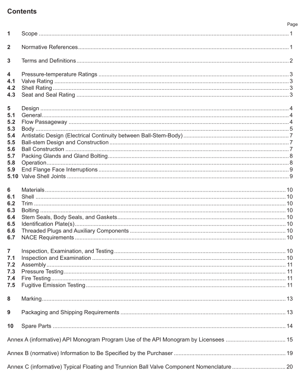
API Std 608 pdf download Metal Ball Valves—Flanged, Threaded, and Welding Ends
5.7Packing Glands and Gland Bolting
5.7.1 Adjustable packing glands shall be accessible for resealing stem packing without the disassembly of vaveparts or operator parts.
5.7.2 Packing glands that are threaded into bodies or covers or onto stems shall not be used for valve sizesgreater than DN 80(NPS 3) unless othewise specified by purchase order.(See Figure C.1 and Figure C.2 forparts identification.)
5.7.3 Vertically split glands shall not be used.
5.7.4 When used, gland bolts shall pass through holes in the packing gland. The use of open slots is notpermitted on any portion of the packing gland.
5.7.5 As a minimum, packing gland bolts shall be designed so that the boltstress shall not exceed one-third ofthe ultimate tensile strength of the bolting material when compressing packing material to a compressive stressof 38 MPa(5500 psi) at 38 °C(100°F).
5.8Operation
5.8.1 Unless otherwise specified on the purchase order, manually operated valves shall be equipped with lever-type handles.
5.8.2 Gear operators shall be fitted with handwheels and shall be sized to comply with the requirements of5.8.3.
5.8.3 Unless othervise specified in the purchase order, the length of the lever handle or the gear ratio,efficiency,and handwheel diameter of gear operators shall be designed so that the required input force to fully openand close the valve shall not exceed 360 N(80 lb) when operating the valve at the manufacturer’s maximumpublished torque as described in 5.5.4.
5.8.4 Valves shall be closed by rotating the closure device (lever or handwheel) in a clockwise direction.5.8.5 Position stops shall be provided for both fully open and fully closed positions of the valve.
5.8.6 Handwheels on manual gear operators shall be marked to indicate the direction of opening and/or closing.5.8.7 Lever-type handles shall be parallel to the ball bore so that the lever always indicates the ball bore position.lf the purchase order specifies round or oval direct-mounted handwheels, a permanent means of indicating theball bore position shall be included in the handwheel design.
5.8.8 An indication parallel with the position of ball bore of the valve shall be integral with the valve stem. Thisindication may be by permanent marking to the top of the stem, keyways, or by the shape of the exposed stemportion.
5.8.9 Levers, handwheels, and other operating mechanisms shall be fitted so that they may be removed andreplaced without affecting the integrity of the stem seal(s), body seal(s), or stem retention means.
5.8.10 Lever or manual gear operators shall be designed so that the lever or gear operator cannot be assembledto the valve other than in the correct configuration to indicate open and closed positions.
5.8.11 When specified in the purchase order,valves shall be furnished with a lockable device that accepts apurchaser-supplied padlock that allows the valve to be locked in both the fully open and fully closed positions.The lockable device shall be designed such that a lock with an 8-mm (%/r-in.) diameter shank not more than 102mm (4.0 in.) long can be inserted directly through hole(s) in lockable device and locked.Provision for lockabledevice is permitted, even when not specified on purchase order.
5.8.12 Position stops integral with packing gland, gland fange, or gland bolting shall not be used.
5.8.13 Direct mounted gear operators, actuators, and extension mounted actuators shall be designed or provided with a means of preventing pressure buildup in the mechanism resulting from stem packing, stem seals, or bonnet seal leakage. Such designs shall also provide self-draining capability to prevent liquid buildup onto gland seals and gland bolting.
5.8.14 Pressed steel handwheels on gear operators are not allowed.
5.8.15 Gear operators, actuators, and extension mounted actuators shall be bolted to the valve and removable without requiring the loosening or removal of the cover bolting, packing gland bolting, or other valve assembly bolting that would expose the valve to leakage while under pressure.
5.9 End Flange Face Interruptions
5.9.1 Ring-shaped radial gaps in the faces of end fanges of fanged ball valves, located in the sealing surface of a centered ASME B16.20 spiral-wound gasket, shall not exceed 0.75 mm (0.030 in.); see dimension “b” in Figure 1. An example of this condition is the radial gap that exists between the outer diameter of a body insert and the inner bore of the body end fange of a valve as shown in Figure C.1.
5.9.2 For ball valves designed with a body insert as shown in Figure C.1, with a gasket seating face outer diameter located within the sealing area of a centered ASME B16.20 spiral-wound gasket, the body insert fange face shall not protrude beyond the valve body end fange face. The body insert fange face shall not be recessed below the body end fange face by more than 0.25 mm (0.010 in.). See dimension “a” in Figure 1.
