API St 608 pdf download
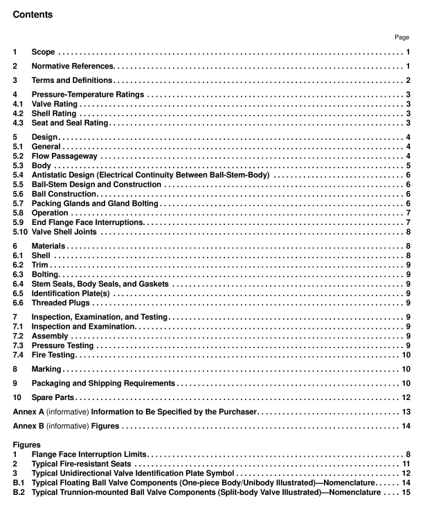
API St 608 pdf download Metal Ball Valves—Flanged, Threaded, and Welding Ends
5.3.9 Upstream sealing, trunnion-mounted ball valves shall have a test port into the body cavity between seats toallow seat testing as specified in APl 598. This test port shall have taper pipe threads in accordance withASME B.1.20.1 and shall be fited with a solid test plug conforming to ASME B16.11. Additional tapped openings arepermitted only when specified in the purchase order and shal have taper pipe threads in accordance withASME B.1.20.1.
5.3.10 lf drain, bypass, or other types of auxilliary connections are specified in the purchase order, they shall complywith the requirements of ASME B16.34.
5.3.11 When specitied in the purchase order, body cavity overpressure shall be in accordance with ASME B16.34.5.4Antistatic Design (Electrical Continuity Between Ball-Stem-Body)
Valves shall incorporate an antistatic feature that insures electrical continuity between the stem and body of valves≤DN 50(
5.5 Ball-Stem Design and Construction
5.5.1The valve shall be designed to ensure that if a failure occurs at the stem-to-ball connection or of the stem itseltwithin the pressure boundary, no portion of the stem is ejected by internal pressure.
5.5.2The torsional strength of both the stem-to-ball connection and the portion of the stem within the pressureboundary (below top of packing) shall exceed the torsional strength of the stem portion above the pressure boundary(above the top of the packing) by at least 10 % at the maximum valve rated temperature.
5.5.3 The stem and the ball-to-stem connection shall be designed such that no pemanent deformation occurs andno failure of any part occurs when a force applied to the lever or gear operator handvheel produces a torque equal tothe greater of:
-20 N-m (15 ft-lb) or
-twice the manufacturer’s maximum published torque.
The manufacturer’s maximum published torque shall be based upon clean, dry air service at the maximum differentialpressure rating of the vallve.
5.6Ball Construction
Ball shall have a cylindrical bore and shall be of solid one-piece construction.Other constructions such as “hollow -type, cored cavity, or sealed cavity may be fumished only if agreed to by the purchaser.
5.7Packing Glands and Gland Bolting
5.7.1 Adjustable packing glands shall be accessible for resealing stem packing without the disassembly of valveparts or operator parts.
5.7.2 Packing glands that are threaded into bodies or covers or onto stems shall not be used for valve sizes greaterthan DN 80 (NPs 3) unless otherwise specified by purchaser.(See Figure B.1 and Figure B.2 for parts identification.)5.7.3 Vertically split glands shall not be used.
5.7.4 When used, gland bolts shall pass through holes in the packing gland. The use of open slots is not permittedon any portion of the packing gland.
5.7.5 Packing gland bolts shall be designed so that the bolt stress shall not exceed 1/s of the ultimate tensilestrength of the bolting material when compressing packing material to a compressive stress of 38 MPa (5500 PSl) at38 C(100°F).
5.8Operation
5.8.1 Unless otherwise specified on the purchase order, manually operated valves shall be equipped with lever-typehandles.
5.8.2 Gear operators shall be fitted with handwheels and shall be sized to comply with the requirements of 5.8.3.
5.8.3 Unless otherwise specified by the purchaser, the length of the lever handle or the gear ratio, efficiency, andhandwheel diameter of gear operators shall be designed so that the required input force to fully open and close thevalve shall not exceed 360 N (80 lb) when operating the valve at the manufacturer’s maximum published torque asdescribed in 5.5.3.
5.8.4 Valves shall be closed by rotating the closure device (lever or handwheel) in a clockwise direction.5.8.5 Position stops shall be provided for both fully open and fully closed positions of the valve.
5.8.6 Handwheels on manual gear operators shall be marked to indicate the direction of opening andor closing.5.8.7 Lever-type handles shall be parallel to the ball bore so that the lever always indicates the ball bore position. Ifthe purchaser specifies round or oval direct-mounted handwheels, a permanent means of indicating the ball boreposition shall be included in the handwheel design.
