API St 520-2 pdf download
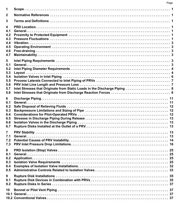
API St 520-2 pdf download Sizing, Selection, and Installation of Pressure-relieving Devices Part II—Installation
1Scope
This standard covers methods of installation for pressure-relief devices (PRDs) for equipment that has amaximum allowable working pressure (MAWP) of 15 psig (1.03 barg or 103 kPAg) or greater. Pressure-reliefvalves(PRVs) or rupture disks(RDs) may be used independently or in combination with each other toprovide the required protection against excessive pressure accumulation.As used in this standard, the termpressure-relief valve includes safety-relief valves used in either compressible or incompressible fuid service,and relief valves used in incompressible fluid service. This standard covers gas,vapor, steam, two-phase,and incompressible fluid service; it does not cover special applications that require unusual installationconsiderations.
2Normative References
The following referenced documents are indispensable for the application of this document.For datedreferences,only the edition cited applies.For undated references,the latest edition of the referenceddocument (including any amendments) applies.
API Standard 520,Sizing,Selection,and lnstallation of Pressure-relieving Devices,Part l-Sizing andSelection
3Terms and Definitions
The terminology for PRDs that is used in this standard is in general agreement with the definitions given inAPI520,Part i.
4PRD Location4.1General
There are a number of design factors that should be considered when determining the location of the PRD.4.2Proximity to Protected Equipment
lf other factors permit, the PRD should normally be placed close to the protected equipment or system ofequipment so that the pressure in the protected equipment stays within code allowable limits and to avoidPRv instability (see Section 7).
See 7.3.3 for guidance on establishing set pressure if PRD will be remote from the protected equipment.4.3Pressure Fluctuations
The PRD should not be located where there are pressure fluctuations large enough to result in relief valvesimmeringlactivation or rupture disk fatigue. On installations that have pressure fluctuations that peak closeto the set pressure of the PRV or burst pressure of a rupture disk, the PRD should be located farther fromthe source and in a more stable pressure region.
Examples of areas that may have pressure fluctuations include:
— locations close to control valves, other valves, and other appurtenances;
— locations close to orifice plates and flow nozzles;
— locations close to other fittings, such as short radius elbows;
— locations close to the discharge of positive displacement pumps or compressors.
The potential effect of pressure fluctuations on the relief device may be reduced by the following (see Figure 1):
— locating the PRD 10 or more pipe diameters from any areas as described above;
— providing a well-rounded, smooth branch connection where the relief device inlet piping joins the main piping run;
— providing a larger branch connection (relative to the size of the PRV inlet).
4.4 Vibration
Most vibrations that occur in piping systems are random and complex. These vibrations may cause leakage at the seat of a PRV, premature opening, or premature fatigue failure of certain valve parts or piping.Vibration in rupture disk piping may adversely affect the burst pressure and life of the rupture disk.
Detrimental effects of vibrations on the PRD can be reduced by addressing the cause of vibrations, by additional piping support, by use of either pilot-operated relief valves or soft-seated PRVs, or by providing greater PRD operating margins.
4.5 Operating Environment
When locating PRDs, consideration should be given to process conditions that could affect PRD reliability.
Locating a PRD in a cleaner or cooler portion of the process may be preferable.
4.6 Free-draining
The PRD inlet and outlet piping should be free-draining (no pockets) away from the PRD. See Section 11.
4.7 Maintainability
The PRD should be installed in a location that facilitates access and maintenance.
5 Inlet Piping Requirements
5.1 General
For general requirements for inlet piping, see Figure 2, Figure 3, Figure 4a, and Figure 4b.
5.2 Inlet Piping Diameter Requirements The nominal size of the inlet piping and fittings shall be the same as or larger than the nominal size of the pressure-relief valve inlet connection as shown in Figure 2 and Figure 3. When two or more active pressure-relief valves are placed on one connection, the inlet internal cross- sectional area of this connection shall be sized to avoid restricting flow to the pressure-relief devices or made at least equal to the combined inlet areas of the in-service pressure-relief devices connected to it. The flow characteristics of this upstream system shall be such that the pressure drop will not reduce the relieving capacity below that required, or adversely affect the proper operation, of the pressure-relief valve.
