API Spec 8A pdf download
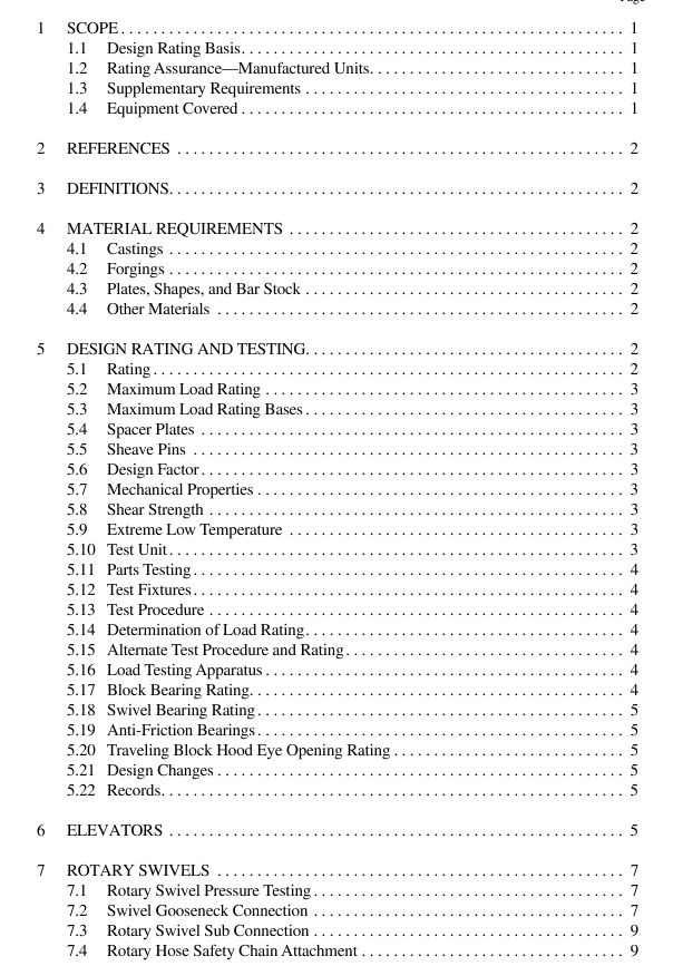
API Spec 8A pdf download Specification for Drilling and Production Hoisting Equipment
4 Material Requirements
4.1 CASTINGS Steel castings used in the manufacture of the main load carrying components of the equipment covered in this specifi- cation shall conform to ASTM A781: Common Requirements for Steel and Alloy Castings for General Industrial Use , and either an individual material specification listed therein or a proprietary material specification that as a minimum con- forms to ASTM A781.
4.2 FORGINGS Steel forgings used in the manufacture of the main load carrying components of the equipment covered in this spec- ification shall conform to ASTM A668: Steel Forgings, Car- bon and Alloy, for General Industrial Use and ASTM A788: Steel Forgings, General Requirements. A material specifica- tion listed in ASTM A788 or a proprietary specification con- forming to the minimum requirements of ASTM A788 may be used. 4.3 PLATES, SHAPES, AND BAR STOCK Structural material used in the manufacture of main load carrying components of the equipment covered in this specifi- cation shall conform to applicable ASTM or API specifica- tions covering steel shapes, plates, bars, or pipe, or a proprietary specification conforming to the minimum require- ments of applicable ASTM or appropriate standard. Struc- tural steel shapes having a specified minimum yield strength less than 33,000 psi, or steel pipe having a specified mini- mum yield strength less than 35,000 psi shall not be used.
4.4 OTHER MATERIALS Other materials may be used in the main load carrying components of equipment, provided the suitability of the material for a particular use has been verified by testing and the material conforms to a written specification. 5 Design Rating and Testing 5.1 RATING All hoisting equipment furnished under this specification shall be rated in accordance with the requirements specified herein. Such ratings shall consist of a maximum load rating for all items, and a main-bearing rating for traveling blocks and swivels. The traveling block ratings are independent of wire rope size and strength. Note: Such ratings shall be calculated as specified herein and in accordance with good engineering practices. The ratings determined herein are intended to apply to new equipment only.
5.2 MAXIMUM LOAD RATING The maximum load ratings shall be given in tons (2,000 lbs units). The size class designation shall represent the dimensional interchangeability and the maximum rated load of equip- ment specified herein. The recommended size classes are as follows:
For purpose of interchangeability contact radii shall com- ply with Table 3.
5.3 MAXIMUM LOAD RATING BASES The maximum load rating will be based on (a) the design safety factor as specified in 5.6 and (b) the yield strength of the material as specified in 5.7 and 5.8.
5.4 SPACER PLATES Spacer plates of traveling blocks, not specifically designed to lend support to the sheave pin, shall not be considered in calculating the rated capacity of the block.
5.5 SHEAVE PINS In calculations transferring the individual sheave loads to the pins of traveling blocks, these loads shall be considered as uniformly distributed over a length of pin equal to the length of the inner bearing race, or over an equivalent length if an inner race is not provided.
5.6 DESIGN FACTOR The design safety factors shall be calculated as follows (See Figure 1) for the relationship between the design safety factor and rating:
