API SPEC 10F pdf download
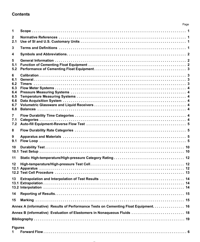
API SPEC 10F pdf download Cementing Float Equipment Testing
Float equipment may be used for lessening the load on the drilling rig or reducing running forces. Since float equipment blocks flow up the casing, the buoyant force acting on casing reduces the load the rig is required to carry. This can be achieved through managing the hydrostatic pressure inside the casing relative to the hydrostatic pressure outside the casing, either through managing fluid height or fluid density. Auto-fill float equipment is a special type of float equipment that allows the casing to fill from the bottom as the casing is run into the well. This may help reduce pressure surges as the casing is lowered into the well. Auto-fill float equipment may help ensure that the collapse pressure of the casing is not exceeded. Once the casing is run, the auto-fill float equipment check valve mechanism is activated, and the float equipment is converted to “standard” equipment. The conversion is normally executed by either pumping a surface- released ball through the equipment or by circulating above a predetermined rate.
5.2 Performance of Cementing Float Equipment There are a number of performance criteria that may be used to evaluate the suitability of a particular piece of float equipment for a given well. Float equipment should function after a fluid containing solids has been circulated through the equipment for a period of time. Flow period, flow rate, fluid temperature, and fluid properties can affect the durability of the equipment. Float equipment should be capable of withstanding a differential pressure with the higher pressure being exerted from below the check valve, and capable of functioning at the temperature to which it is exposed. The testing procedures consist of:
a) flow durability; b
) static pressure and temperature testing. The flow durability tests entail installing the float equipment in a flow loop and pumping a specified test fluid for a set amount of time. This is followed by applying a low backpressure to determine if the valve holds pressure. If casing fill-up equipment is being evaluated, the equipment is subjected to reverse flow of fluids for a specified time and then converted prior to testing forward flow. Following the flow durability tests, the float equipment is mounted in an apparatus that allows the equipment to be heated to elevated temperature and backpressure applied to determine if the valve leaks. This standard does not address flow or testing with fluids in a gaseous state.
6 Calibration
6.1 General This clause defines the requirements for calibration and verification of measurements by instruments and acquisition systems used in testing cementing float equipment. The term “calibration” is used to mean either calibration or verification according to the requirements of this specification. Prior to running a test, calibrations shall be performed using instruments and devices certified and traceable to a national/international body, such as NIST, EN, ISO, or equivalent, within the previous 12 months. Equipment calibrated to the requirements of this specification is considered accurate if calibration is within the specified limits listed in 6.2 through 6.8. Calibration dates for instruments used in the tests of cementing float equipment shall be recorded on the test report.
6.2 Timers Timers shall be accurate within ±5 seconds per hour and shall be verified over a period of no less than 12 minutes. Calibration shall use the time signal from the NIST or similar websites and radio stations. If not within required accuracy, the units shall be adjusted or replaced.
6.3 Flow Meter Systems The flow meter system shall be capable of measuring the flow rate of the circulating test fluid being pumped through the float equipment in 0.015 m 3 /min (0.1 bbl/min) or smaller increments and be accurate within ±0.015 m 3 /min (±0.1 bbl/min) for the flow rate of the test being performed. Turbine-type flow meters are susceptible to wear and may not be suitable to the tests in this specification. Turbine-type flow meters shall be volumetrically calibrated after each test. If the flow meters are found to be outside of the above accuracy, the test is invalid.
6.4 Pressure Measuring Systems Pressure measuring systems shall be readable to ±0.5 % of the test pressure range or better and cover the range to be measured. The system shall be able to maintain ±2 % accuracy of the test pressure range. Calibration shall be done at 25 %, 50 %, 75 %, and 100 % of test pressure, using a certified deadweight tester or master gauge to ±1 % of full range or minimum gauge increment, whichever is greater.
