API RP 545 pdf download
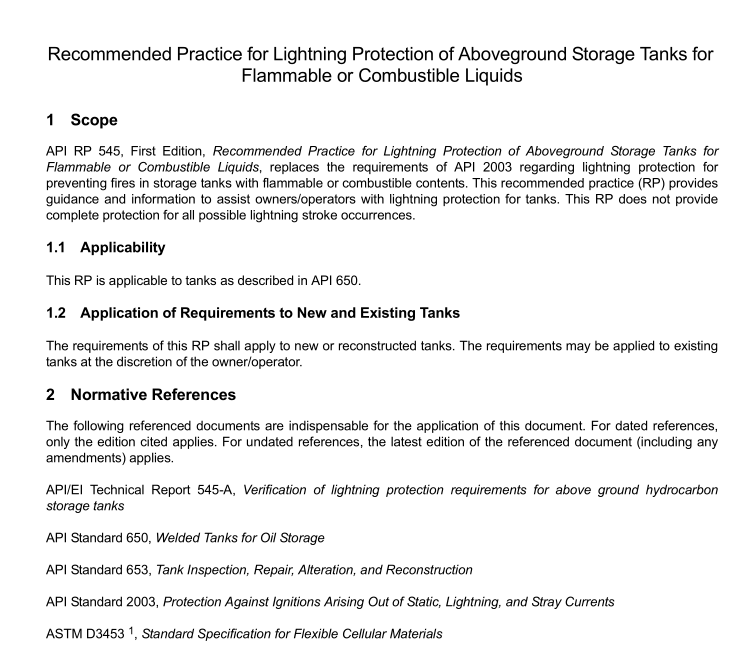
API RP 545 pdf download Recommended Practice for Lightning Protection of Aboveground Storage Tanks for Flammable or Combustible Liquids
4Protection of Specific Types of Tanks
4.1Fixed-roof Tanks (Metallic) and Tanks with Internal Floating Roofs
For fixed roof tanks (metallic cone or dome) and internal floating-roof tanks (IFRTs), there is a possibility of flammablevapors being present at atmospheric vents. If present,flammable vapors can be ignited by a lightning flash.
Shunts or bypass conductors are not required for lightning protection.Bonding techniques to prevent static dischargebetween the floating roof and shell are addressed in API 650,Appendix H.
Tanks handling low vapor pressures or in-service with properly maintained floating roofs with tight-fitting seals are notlikely to have fiammable vapors at atmospheric vents unless it is being refilled from empty. In these cases, no furtherlightning protection is required (see Annex B).
4.2External Floating Roof Tanks
4.2.1Bonding Between Floating Roof and Shell4.2.1.1 Shunts for Conduction
4.2.1.1.1 General
Shunts are used for conduction of fast and intermediate duration components of lightning-stroke current.4.2.1.1.2 Number and Placement
The shunt to shell contact point shall be submerged at least 0.3 m (1 ft) below the surface of the liquid product. Theshunt shall have as short and direct a path as possible from the conductive floating roof to the tank shell.The shuntsshall be spaced at intervals no greater than 3 m (10 ft) around the perimeter of the floating roof.When retrofittingexisting tanks with submerged shunts, the abovedeck shunts shall be removed.
4.2.1.1.3 Cross-sectional Area-Minimum Width and Material
The shunts shall consist of an austenitic stainless steel conductor of at least 20 mm2(0.031 in.2) cross-sectional area,or of other material conductors of equivalent current-carrying capacity and corrosion resistance. The minimum widthof the shunt shall be 51 mm (2 in.).The shunts shall be of the minimum length necessary to permit the function of thefloating-roof seal assembly. The shunts shall be of the minimum length necessary to remain in contact with the shellduring the full horizontal and vertical design movement of the floating roof.
4.2.1.1.4 Durability
The shunts and termination connections shall be of sufficient flexility, cross-sectional area, and corrosion resistanceto have a minimum service life of 30 years.
4.2.1.2 Bypass Conductors
4.2.1.2.1 General
Bypass conductors are used for conduction of the intermediate and long duration component of lightning-strokecurrent.
4.2.1.2.2 Number,Length and Electrical Resistance
The tank floating roof shall be bonded to the tank shell by direct electrical connection through an appropriate numberof bypass conductors.Each conductor, including connections, shall have a maximum end-to-end electrical resistanceof 0.03 2. The bypass conductors shall be of the minimum length necessary to permit full movement of the floatingroof. Bypass conductors should be evenly spaced not more than every 30 m (10o ft) around the tank circumferencewith a minimum of two.
4.2.1.2.3 Durability
The bypass conductors and termination connections shall be positioned and of suficient flexibility, cross-sectionalarea, and corrosion resistance to have a minimum service life of 30 years.
4.2.2 Parallel Conducting Paths(Seal Assembly from the Floating-roof Tank)
Any non-fully submerged conductive seal assembly components including springs,scissor assemblies,sealmembranes, etc.shall be electrically insulated from the tank roof. The insulation level shall be rated 1 kV or greater.
NOTE This allows any lightning discharge current from the floating roof to the tank shell to take the preferential path through theshunts and bypass conductors.
4.2.3 lnsulation of Gauge or Guide Poles
Any gauge or guide pole components or assemblies that penetrate the tank floating roof shall be electrically insulatedfrom the tank floating roof.The insulation level shall be rated 1 kV or greater.
NOTE This allows any lightning discharge current from the floating roof to the tank shell to take the preferential path through theshunts and bypass conductors.
5Metal Thickness
Minimum metal thicknesses for tanks are provided in API 650 and APl 653.
Additional information is presented in EIAP1 545-A, Verification of lightning protection requirements for above groundhydrocarbon storage tanks.
