API RP 14B pdf download
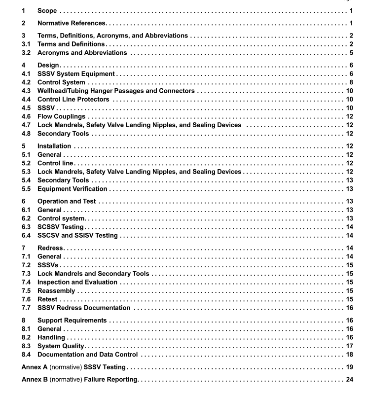
API RP 14B pdf download Design, Installation, Operation, Test, and Redress of Subsurface Safety Valve Systems
4.1.3 Interfaces Equipment shall be selected and verified as being compatible with the dimensions and configurations of: tubing and auxiliary conduit connections; tubing and casing drift diameters; related permanent well equipment and well-servicing tools; and control or other fluids in contact with the equipment.
4.1.4 Pressures/Temperatures/Flow Rates/Loads Equipment shall be selected and verified to meet or exceed the anticipated pressure range, temperature range, maximum/minimum flow rates, and anticipated loading conditions.
4.2 Control System
4.2.1 General All elements of the control system shall be analyzed for potential hazards that may render the system vulnerable to failure or may preclude safe use. For example, automatic resets shall not be incorporated in the control system since this feature may cause the SCSSV to reopen when it should remain closed. Systems shall be designed and operated to address potential hazards. It is desirable to integrate the SCSSV control system with the surface safety system to ensure the operational sequence as recommended in Annex D. The integrated system shall be designed to allow independent signal supply and control of the SCSSV. This feature will allow for routine maintenance and troubleshooting. For multiple-well installations, the control-system manifolding should include provisions for individual well and SCSSV isolation. Emergency shut-down (ESD) controls shall be installed in strategic locations in accordance with API 14C, applicable regulations and sound engineering judgment.
To avoid closure of the SCSSV under full well-flow conditions, a delay shall be incorporated between closure of the tree valves controlled by the ESD and the downhole SCSSV. The opening sequence should be reversed on returning production facilities to normal operations. This delay mechanism shall be analyzed and documented to verify that it does not create hazards that render the system vulnerable to failure. NOTE API 17F contains information relating to subsea production control systems.
4.2.2 Sensors Each installation shall be analyzed to determine applicable sensors. The sensor types used to signal the SCSSV may include heat sensors, pressure sensors, fluid level sensors, and other sensors, as applicable. A high/low level sensor may be placed on the supply tank of hydraulic systems to warn of abnormal operating conditions, e.g. well flowing through control line or a leaking control line. A low-pressure pilot may also be installed on the control system pump discharge.
4.2.3 Power The system shall be designed with sufficient capacity to operate all equipment to the defined conditions of the application.
The following requirements apply to various types of control systems:
a) Monitoring and controls shall be incorporated to prevent exceeding the limitations of the system.
b) The control conduit shall have adequate considerations for returned control signals upon closure of the SCSSV.
4.2.4 Guidelines for Selection of Control Fluid
The following shall be considered when selecting control fluids:
a) equipment supplier/manufacturer’s recommendations;
b) flammability;
c) flash point;
d) lubricity;
e) physical/chemical compatibility: the fluid shall not degrade the sealing elements resulting in hardening, softening,swelling, or shrinking;
f) fluid property stability over expected temperature/pressure ranges and service life;
g) fluid cleanliness (solids content);
h) foam inhibition;
i) toxicity (including environmental impacts);
j) low corrosiveness;
k) oxidation stability;
l) viscosity and specific gravity at the operating temperatures.
4.2.5 Guidelines for Selection of Control Line
The following shall be considered when selecting the control line:
a) temperature at the SCSSV;
b) completion fluid (annulus);
c) anticipated operating pressures (maximum, minimum; internal, external);
d) working pressure of surface wellhead;
e) safety valve setting depth;
f) geometrical constraints;
g) control media, such as hydraulic fluid, pneumatic fluid, or an electric signal;
h) control line connector design, material and pressure rating;
i) control line manufacturing technique;
j) supplier/manufacturer’s minimum bend radius;
k) well environment;
l) control line encapsulation/protection.
