API MPMS 6.2 pdf download
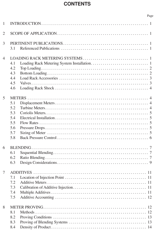
API MPMS 6.2 pdf download Manual of Petroleum Measurement Standards Chapter 6—Metering Assemblies Section 2—Loading Rack Metering Systems
4.5.3 Check Valves Check valves are required to prevent backflow, siphoning with low tank head, and cross contamination of product during blending applications. When choosing the proper check valve, consider pressure drop and slamming of the flapper, which can cause damage when the valve opens and closes.
4.5.4 Flow Control Valves Flow control valves must be installed downstream of the meter. These valves should provide a smooth opening and closing and be capable of stable flow control. Additionally, quick operation is required to prevent overfill. The manufacturer’s recommended flow control range should not be exceeded. This could result in poor flow control, unsafe shutoff, inaccurate measurement, and premature wear. The flow control valve is typically controlled by an elec- tronic preset to reduce the discharge rate at start-up or before shutdown, to control the delivery rate and to shut off the flow at the conclusion of the delivery. Because most flow control valves depend on differential pressure for proper operation, care should be taken to ensure that operating pressures pro- vide for adequate speed of operation.
4.6 LOADING RACK SHOCK Severe shock to loading rack systems can occur unless cer- tain precautions are taken in the design of the rack delivery facilities, in the construction of the facilities, or in both. Clos- ing the loading or control valve too rapidly causes this shock, called hydraulic hammer. It should be avoided by controlling the closing rate of the valve involved. Emergency shutdown of a bottom loading rack initiated by a high-level shutdown device must be accomplished in a time frame that will prevent overflow. The use of slow-closing valves or the control of the closing rate on the loading arms is recommended to reduce line shock. The occurrence and severity of line shock depend on flow rate, shutdown rate, and length and size of lines. When preset devices are used, a two-stage start-up-and-shutdown valve should be incorporated to start the flow slowly before it allows full flow to develop and to slow the flow down shortly before the final shutoff.
5 Meters This section covers the characteristics of loading rack meters and discusses only those considerations unique to the design, selection, installation, and performance for refined product truck loading. Historically, truck loading racks were designed for use with displacement meters; however, technological advances and blending applications have encouraged the introduction of other meter designs such as turbine and Coriolis meters. When retrofitting existing displacement metering systems with turbine and Coriolis meters, care should be taken to ensure proper application of these technologies. At a mini- mum, to ensure proper operating performance, meters should be installed according to manufacturers’ recommended prac- tices. Make certain that any areas that may trap or build up with debris are avoided. Avoid installing the meter at a high point in the piping to prevent trapping air in pockets and causing problems with equipment and perhaps creating safety issues.
5.1 DISPLACEMENT METERS Displacement meters (API MPMS Ch. 5.2) will require some form of signal output, either mechanical or electronic. Note that whenever a meter with a manual calibrator mounted below the pulser is retrofitted with an electronic pulse output device, the calibrator must be removed. Displacement meters typically can be mounted either verti- cally or horizontally. Consult the manufacturer for proper ori- entation or issues of bearing load and wear. Displacement meters do not require flow conditioning. See Figure 3 for a typical installation.
5.2 TURBINE METERS The performance of turbine meters (API MPMS Ch 5.3) is affected by liquid swirl and non-uniform velocity (laminar) profiles that are induced by upstream and downstream piping configurations, valves, pumps, joint misalignment, protruding gaskets, welding projections, additive injection points, ther- mowell or other obstructions. Flow conditioning shall be used to overcome swirl and non-uniform velocity profiles. Upstream flow conditioning requires the use of a flow conditioning plate, sufficient length of pipe, or a combination of straight pipe and straightening elements. Flow conditioning is required downstream of the meter; generally, five pipe diame- ters is recommended.
A flow conditioning plate is a perforated plate or wafer that has a unique geometric pattern of holes or openings to pro- vide flow conditioning with a minimum use of space. Flow conditioning plates provide a uniform flow distribution with low turbulence intensity and are designed to eliminate swirl and produce a fully developed velocity flow profile. They function by greatly reducing the scale of turbulence into a large number of small disturbances, which coalesce and rapidly diminish. The position, size and number of holes in the plate are designed to provide a uniform velocity profile. Any misalignment of the plate could cause errors in registration. Manufac- turers often design plates as an integral part of the turbine meter design to ensure alignment. Due to possible misalign- ment, caution is recommended for plates that bolt between flanges and are not integral to the turbine meter. Periodic inspection of the plate is necessary to prevent fouling, plug- ging or distortion. Any disturbance of the plate requires that the meter be re-proved.
