API 520-2 pdf download
API 520-2 pdf download Sizing, Selection, and Installation of Pressure-relieving Devices Part II—Installation
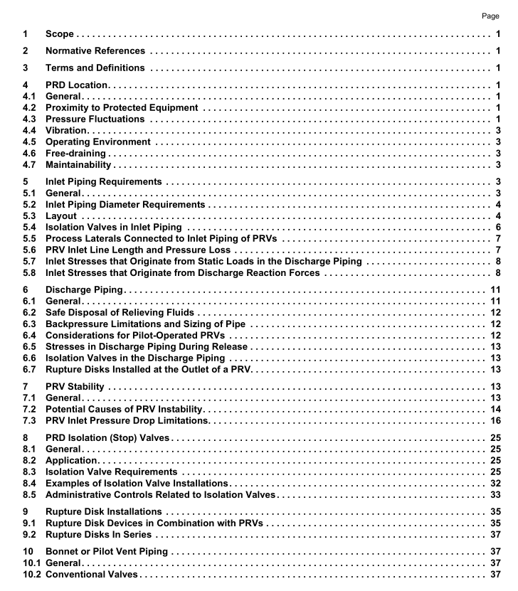
6.2 Safe Disposal of Relieving Fluids For a comprehensive source of information about the safe disposal of various relieving fluids, see API 521 [3] .
6.3 Backpressure Limitations and Sizing of Pipe
6.3.1 General When discharge piping is designed, consideration should be given to the combined effect of superimposed and built-up backpressure on the operating characteristics of the PRDs. The discharge piping system should be designed so that the backpressure does not exceed an acceptable value for any PRD in the system. See API 520, Part I for limitations on backpressure. The rated capacity corrected for the actual overpressure of a conventional spring-loaded, balanced spring- loaded, or pop-action pilot-operated PRV should typically be used to size the atmospheric vent piping or the discharge line from the PRV to the relief header. Note that the rated capacity corrected for the actual overpressure can vary depending on the overpressure scenario. Common relief header piping in closed discharge systems can be sized using the protected system’s required relieving capacity (see API 521).
For a modulating pilot-operated PRV, the discharge piping can be sized using the required relieving capacity of the system that the valve is protecting. Whenever the atmospheric vent, discharge piping, or common relief header piping is sized using the system’s required relieving capacity instead of the rated capacity of the valve corrected for the actual overpressure, the backpressure should be re-checked whenever changes are made to the process that affect the required relieving capacity of the system the valve is protecting. For pressure drop calculations, when discharging incompressible or subsonic compressible flow to either a closed reservoir or the atmosphere, the static pressure within the exit of the pipe is numerically equal to the reservoir or atmospheric pressure, respectively. When discharging sonic compressible flow, the pressure within the exit of the pipe is the calculated choking pressure. [8] Additional information on sizing of discharge piping systems for vapor or gas service is covered in API 521 [3] .
6.3.2 Thermal Relief Valves The discharge piping from thermal relief valves designed solely to protect against liquid hydraulic expansion due to ambient heating (including solar radiation) typically does not need to be sized to meet the built-up backpressure limits provided in API 520, Part I and as discussed in 6.3.1. The reason for this is that the capacity of these PRVs is typically larger by an order of magnitude (>10 times) than the required relief rate and the flow in the discharge line never reaches a steady state flow at the capacity.
See 7.3.8 for additional discussion and cautions with thermal relief valves. Examples where outlet pressure drop calculations for thermal expansion generated by ambient heating would be considered applicable are for a long pipeline or large liquid-filled vessel, where the required flow rate due to thermal expansion approaches the rated capacity of the valve corrected for the actual overpressure. The user is cautioned that for liquids (e.g. refrigerated liquids, LPG, or LNG) where blocking in with ambient heating may lead to vaporization and possible overpressure (not thermal relief), required relief rates may be large enough to warrant outlet pressure drop calculations. Discharge piping for thermal relief valves in applications where pressure inside the protected equipment can be generated by process heat should be sized to meet the built-up backpressure limits provided in API 520, Part I.
See 7.3.8 for inlet loss criteria for thermal relief valves.
6.4 Considerations for Pilot-Operated PRVs Superimposed backpressure that exceeds the inlet pressure of a pilot-operated PRV can cause the main valve to open, allowing reverse flow through the main valve. For example, backflow can occur if several PRVs have their outlets manifolded into a common discharge header, and one or more of these valves is discharging while another is connected to a system with a lower inlet pressure. An accessory should be specified that would prevent such backflow.
