ISO 3364 pdf download
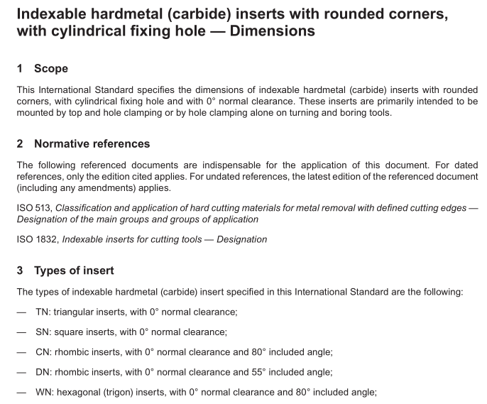
ISO 3364 pdf download ndexable hardmetal (carbide) inserts with rounded corners, with cylindrical fxing hole — Dimensions
Scope
This International Standard specifies the dimensions of indexable hardmetal (carbide) inserts with roundedcorners, with cylindrical fixing hole and with 0°normal clearance. These inserts are primarily intended to bemounted by top and hole clamping or by hole clamping alone on turning and boring tools.
2Normative references
The following referenced documents are indispensable for the application of this document.For datedreferences, only the edition cited applies.For undated references, the latest edition of the referenced document(including any amendments) applies.
ISO513,Classification and application of hard cutting materials for metal removal with defined cutting edges—Designation of the main groups and groups of application
ISO 1832,Indexable inserts for cutting tools —Designation
3Types of insert
The types of indexable hardmetal (carbide) insert specified in this International Standard are the following:_TN: triangular inserts, with O° normal clearance;
-SN: square inserts, with 0° normal clearance;
-CN: rhombic inserts, with 0° normal clearance and 80° included angle;—DN: rhombic inserts, with O° normal clearance and 55° included angle;
-WN: hexagonal (trigon) inserts, with 0° normal clearance and 80° included angle;-VN: rhombic inserts, with 0° normal clearance and 35° included angle.
Inserts covered by this International Standard are standardized with chip breakers on both faces, with chipbreakers on one face only and with no ship breakers at all.
Neither the shape nor the dimensions of chip breakers are standardized.Thus, if necessary, special featuresshall be explained by means of a diagram or additional specifications.
Table B.1 gives the range of sizes for these inserts.
4Interchangeability
4.1Tolerances
Indexable hard metal (carbide) inserts specified in this International Standard are provided in tolerance classesin accordance with lSO 1832.
Other tolerances are given, either in Table 1 for hole dimensions, or in Tables 2 to 7 for insert dimensions.
4.2 Thickness, s, of inserts with chip breakers The thickness, s, of inserts with chip breakers is defned as the distance between the cutting edge at the corner and the opposing supporting surface of the insert; see Figure 1 a) and b) for inserts with chip breakers on one face only and Figure 1 c) for inserts with chip breakers on both faces.
5 Designation and marking
5.1 Designation
The designation of the indexable hardmetal (carbide) inserts complying with this International Standard shall conform to ISO 1832.
In addition to this designation, one or both of the following may be indicated:
— the symbol of the group of application, in accordance with ISO 513;
— the commercial designation of the hardmetal (carbide) grade.
5.2 Marking
The following symbols, at least, shall be marked on the insert itself (except where this is difficult on the smallerinserts):
-symbol of the group of application, or
-commercial designation of the hardmetal (carbide) grade, or-both, if possible, on large inserts.
6 Measurement
Annex B indicates the methods of measuring the dimension, m, of the indexable inserts covered by thislnternational Standard.
7 Recommended dimensions
7.1General
The choice of the more common dimensions is restricted to the specifications given in Tables 2 to 7. lt isstrongly recommended that these standard inserts be used wherever possible (first preference).Where otherinserts are specially required, insert dimensions shall be selected from the non-shaded portions of Table B.1(second preference). Inserts corresponding to dimensions represented by the shaded portions of this table arenot recommended.
7.2Triangular inserts
