ISO 20766-14 pdf download
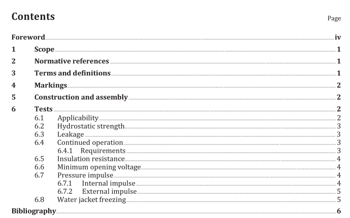
ISO 20766-14 pdf download Road vehicles — Liquefied petroleum gas (LPG) fuel system components — Part 14: Vaporizer/pressure regulator
b) Cycle the inlet pressure of the regulator for 1 % of the total number of cycles at room temperature
from 100 % to 50 % of the working pressure.The duration of each cycle shall be no less than 10 s.c)The regulator shall comply with 6.3-at room temperature at the completion of this test.
d) Repeat the cycling procedure of a) at 120 °C at the working pressure for 1 % of the total number of
cycles.
e) Repeat the cycling procedure of b) at 120 °C at the working pressure for 1 % of the total number of
cycles.The regulator shall comply with 6.3-at 120 °Cat the completion of this test.
f) Repeat the cycling procedure of a) at-40 °Cor-20 °C, as applicable and 50 % of working pressure
for 1 % of the total number of cycles.
g) Repeat the cycling procedure of b) at -40 °C or-20 C, as applicable and 50 % of working pressure
for 1 % of the total number of cycles. The regulator shall comply with 6.3-at -40 °C or -20 °C, asapplicable at the completion of this test.
h) At the completion of the cycles, the lock-up pressure downstream of the regulator shall not exceed
the lock-up pressure specified by the manufacturer.
6.5Insulation resistance
The insulation resistance test is designed to check for a potential failure of the insulation between thetwo-pin coil assembly and the pressure regulator casing.
Apply a test voltage of 500 v d.c. for a duration of 60 s between one pin of the coil and the pressureregulator casing; for coil assemblies with circuitry of 3,8 mm pitch or below, 100 V d.c. shall be used.The minimum allowable resistance shall be >10 MQ.
6.6Minimum opening voltage
The minimum opening voltage at room temperature shall be s8 V for a 12 Vsystem and ≤16 V for a 24Vsystem. The componentshall be pressurized at 0,75 times the working pressure during the test.
6.7Pressure impulse
6.7.1 Internal impulse
Conduct the following steps for the internal impulse test.
a) Subject the pressure regulator with its first stage valve locked in the open position to a suddenapplication of its working pressure at its inlet. The pressure regulator shall retain or release thepressure without any permanent deformation.
b) The lock-up pressure downstream of the regulator shall not exceed the lock-up pressure specified
by the manufacturer.
6.7.2 External impulse
The pressure regulator shall withstand 100 inlet pressure pulses, as follows.
a) If the regulator has an integrated solenoid valve, it shall be opened by application of the rated
voltage.
b) The outlet of the regulator shall be vented until the inlet fuel line is at atmospheric pressure and
then closed.
c)The working pressure shall be instantaneously applied to the regulator inlet.
The pressure regulator shall contain or vent the pressure without any permanent deformation. Thepressure regulator shall meet the requirements of the external leakage in accordance with 6.3, andthe lock-up pressure shall not exceed the manufacturer’s rated lock-up pressure after the 100 inletpressure pulses.
The internal impulse test in 6.7.1 -tests the reaction of the regulator under a pressure pulse that entersinto the first stage chamber, for example, if the pressure regulator has no gas in it, the inlet valve isopen and the cylinder valve opens instantaneously or the system is connected to a filling dispenser.The external impulse test in this subclause tests the resistance of the inlet valve to pulses on the high-pressure side, for example, a pressure regulator with normal working pressure inside but with nopressure in the fuel line and there is a sudden opening of the cylinder valve filled with service pressure.6.8Water jacket freezing
Conduct the following steps for the water jacket freezing test.
a) Attach 1-m sections of coolant hose to the coolant inlet and outlet of the regulator or water jacket.
Fill the regulator or water jacket, which normally contains an antifreeze solution, with water, tonormal capacity and expose it at-40 C± 2 °Cor -20 C± 2°C, as applicable, for 24 h.
b) Following the freezing conditioning,and after exposing the assembly to 20 °C± 2°C for a minimum
of 24 h, conduct an external leakage test at room temperature according to 6.3.
A separate sample may be used for this test.
