IEC 60263 pdf – Scales and sizes for plotting frequency characteristics and polar diagrams
IEC 60263 pdf – Scales and sizes for plotting frequency characteristics and polar diagrams
1Scope
This document specifies standard aspect ratios for logarithmic or level characteristicsexpressed in decibels versus a logarithmic frequency axis and ranges for the radius of polardiagrams of level. Applications include hard copy printouts,electronic files (e.g.,PDF files),scientific publications,screen displays in computer programs and apps,as well as graphs instandards.
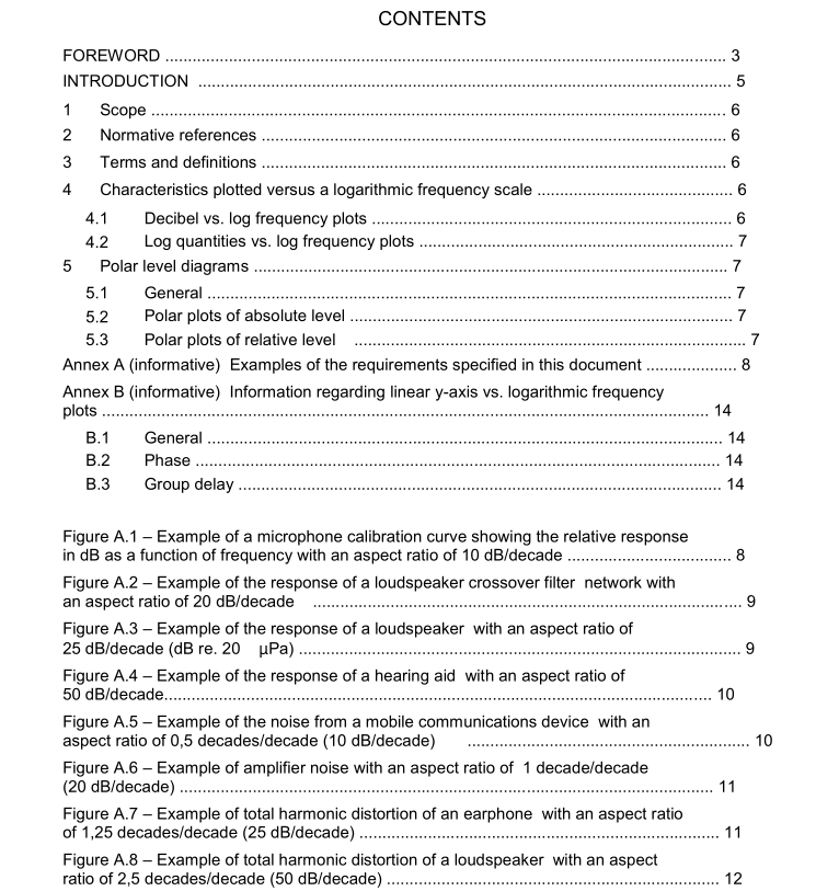
Informative examples of graphs that conform to the requirements in this document are found inAnnex A.
Although outside the scope of this document,graphs with a linear y-axis versus logarithmicfrequency (e.g., phase, group delay, etc.) often accompany the standard aspect ratio graphs of
level described in the normative part of this document These are described in informativeAnnex B.
Normative references
There are no normative references in this document.
3Terms and definitions
For the purposes of this document, the following terms and definitions apply.
lso and IEC maintain terminological databases for use in standardization at the followingaddresses;
. Iso Online browsing platform: available at httpss/www.iso.orglobp.IEC Electropedia: available at http-/www.electropedia.orgl
3.1
aspect ratio
scale proportion between the y-axis and x-axis of a graph
Note 1 to enty. For graphs with a logarithnic frequency x-axis, the aspect ratio is expressed as the y-axis factorper decade (in frequency)for exampleR25 dBNdecade,or 1,25 decadas/decada.
3.2
decade
factor of 10 on a logarithmic scale
Note 1 to enty: For example,500 Hz is 1 decade abowe 50 Hz; 0,01 % lis 3 decades below 10 %.4Characteristics plotted versus a logarithmic frequency scale
4.1 Decibel vs. log frequency plots
For graphs in which the y-axis depicts a level (in decibels) plotted versus lagarithmic frequency
on the x-axis,the aspect ratio shall be 10 dB/decade,20 dB/decade,25 dB/decade or50 dBidecade.
NOTE Direct comparison of hardcopy printouts to older analogue plots is faclitated by ensuring that 1 dB is equalto 1 mm,2 mm,or 5mm,as required.
4.2Log quantities vs. log frequency plots
For graphs in which the y-axis depicts an absolute quantity or a percentage on a logarithmicamplitude scale plotted versus logarithmic frequency’ on the x-axis, the aspect ratio shall be0,5 decades/decade, 1 decade/decade,1,25 decades/decade or 2,5 decades/decade.
NOTE These aspect ratios correspond exactly to the levelequivalents of 10 dB/decade,20 dB/decade,25 dB/decadeand 50 dB/decade in 4.1,respectively.
5 Polar level diagrams
5.1General
Polar level diagrams shall depict level as increasing outward versus radius. The angle ofincidence shall be depicted as increasing moving counterclockwise relative to the referencedirection. The angle assigned to the reference direction shall be 0°. Major angular divisionsshall be plotted as radi at a minimum of 30° intervals and shall be labelled.
5.2Polar plots of absolute level
For a polar plot of absolute level referred to a reference quantity (e.g. dB re.20
uPa), the level
range of the graph shall be 60 dB or 30 dB to the origin.
For polar plots of absolute level with a range of 60 dB to the origin, the maximum level shall beplotted less than 10 dB below the circle of maximum radius. Major level divisions shall be plottedas concentric circles with radii in multiples of 10 dB.Major divisions shall be labelled.Optionalminor divisions are plotted as circles in 2 dB intervals without labels.
For polar plots of absolute level with a range of 30 dB to the origin, the maximum level shall beplotted less than 5 dB below the circle of maximum radius. Major level divisions shall be plotted
as circles with radi in multiples of 5 dB.Major divisions shall be labelled. Optional minordivisions are plotted as circles in 1 dB intervals without labels.
5.3 Polar plots of relative level
For a polar plot of relative level,such as the difference between the absolute level from atransducer and the absolute level in a reference direction, the level range of the graph shall be
30 dB to the origin.The reference circle shall represent a relative level of 0 dB.The referencecircle radius shall be 10 dB,15 dB, or 20 dB or 25 dB. The maximum level shall be plotted lessthan or equal to 5 dB below the circle of maximum radius.Major level divisions shall be plotted
as circles with radi in multiples of 5 dB. Major divisions shall be labelled. Optional minordivisions are plotted as circles in 1 dB intervals without labels.
NOTE The level in the reference direction is o dB.
