BS EN ISO 11807-2 pdf download
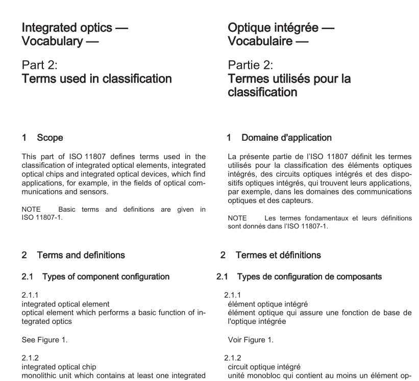
BS EN ISO 11807-2 pdf download Integrated optics — Vocabulary — Part 2: Terms used in classification
1 Scope
This part of ISO 11807 defines terms used in theclassification of integrated optical elements, integratedoptical chips and integrated optical devices, which findapplications, for example, in the fields of optical com-munications and sensors.
NOTEBasic terms and definitions are given inlSO11807-1.
2Terms and definitions
2.1Types of component configuration
2.1.1
integrated optical element
optical element which performs a basic function of in-tegrated optics
See Figure 1.
2.1.2
integrated optical chip
monolithic unit which contains at least one integratedoptical element
See Figure 1.2.1.3
integrated optical device
packaged integrated optical chip
NOTEThe packaging may consist at a minimum ofone optical input and/or output connection and/or electricalconnections and/or a housing.
See Figure 1.
2.2Types of function
NOTEThe types of function defined here are specifiedfor elements,whereby they are valid for all correspondingcomponent configurations.
2.2.1
passive integrated optical element
element based on the principle of waveguiding andradiation interference,respectively,without externalinfluence on the refractive index and fitted exclusivelywith optical inputs and outputs
NOTE This element is employed for changing the di-rection, distributing, combining, transforming and filtering ofguided radiation waves.
2.2.2
controllable integrated optical element
element which can be influenced by various physicaleffects [e.g. electro-optical,acousto-optical,piezo-optical,thermo-optic or electro-absorptive materialcharacteristics which can be used to change the(complex) refractive index]
NOTEln the case of electro-optical control, the refrac-tive index can be changed by the penetration of an electricfield, or acousto-optical control by a surface acoustic wave(SAW).
2.2.3
active integrated optical element
element based on photo-effect and emission
NOTE 1 Functions in this category include the genera-tion of optical signals (conversion of electrical signals intooptical signals), amplification or detection (conversion of op-
tical signals into electrical signals) of guided radiationwaves.
NOTE2lncluded in this category are injection diode la-sers,optical amplifiers and photodetectors integrated withwaveguides.
2.3 Passive elements and chips
2.3.1
slab waveguide
waveguide which confines the radiation only perpen-dicular to the substrate
2.3.2
strip waveguide
element which confines the radiation in a two-dimen-sional cross-sectional area perpendicular to the sub-strate surface along a one-dimensional path
NOTEln general the core or, in the case of a gradedindex profile, the corresponding core area,may be formedas:
%/embedded channel [see Figure 2a)] or buried channel
[see Figure 2b];
%/ridge on a substrate [see Figure 2c)];
3%ridge in a waveguiding layer [see Figure 2d)] or rib on
a waveguiding layer [strip-loaded waveguide; seeFigure 2e)].
2.3.3
branch
element which divides an input strip waveguide intomultiple output strip waveguides
NOTEDepending on the application,a distinction ismade between a divider usually a ‘1″ M divider and a com-biner, usually a N ” 1 combiner.
2.3.4
tap
element which couples a given portion of radiation outof a strip waveguide into another waveguide branch-ing out of the side of the original waveguide
2.3.6
directional coupler
four-port element consisting of a pair ofstripwaveguides in which the fields are mutually coupledand the input and output ends diverge from one an-other
NOTE1The two waveguides may be closely spaced,intersect, or cross each other at an acute angle.
NOTE2The function is based on the principle of peri-odic coupling of radiation by interference.They can be fab-ricated as either a passive or controllableelement.Directional couplers where the waveguides intersect eachother (at an acute angle) are also given the designationx-coupler.
2.3.7
3-dB coupler
four-port element which divides the entering power ofradiation equally between both output waveguides
2.3.8
N M star coupler
element in which the radiant power of Ninputwaveguides is distributed equally amongst M outputwaveguides
NOTEThe star coupler can be configured from net-worked Y-branches and/or 3-dB couplers or a multi-modewaveguide section.
2.3.9
waveguide intersection
element consisting of two strip waveguides which in-tersect one another
NOTE1If the angle of intersection is large enough (idealcase 90 ), then no mutual interference occurs between theguided waves in the individual waveguides.
NOTE2lf the angle of intersection is small,then cou-pling occurs (cf.2.3.6 directional coupler); this element is
then referred to as an X-coupler.
2.3.10
waveguide offset
abrupt lateral displacement of the waveguide borderwhich can lead to a disturbance of the propagated ra-diation,or,at the transition between waveguide sec-tions of different or opposite curvature, can be used toimprove field overlapping
