IEC 63115-2 pdf – Secondary cells and batteries containing alkaline or other non-acid electrolytes – Sealed nickel-metal hydride cells and batteries for use in industrial applications – Part 2: Safety
IEC 63115-2 pdf – Secondary cells and batteries containing alkaline or other non-acid electrolytes – Sealed nickel-metal hydride cells and batteries for use in industrial applications – Part 2: Safety
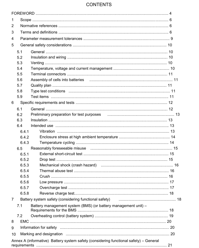
5 General safety considerations5.1General
The safety of sealed nickel-metal hydride cells or batteries requires the consideration of twosets of applied conditions:
a) intended use;
b) reasonably foreseeable misuse.
The manufacturer can use “cell block(s) or monobloc(s)” instead of “cell(s)” for any test thatspecifies “cell(s)”. The manufacturer can use “battery pack” instead of “battery” as the test unit
in this document.The cell manufacturer shall clearly declare the test unit for each test.
Cells or batteries shall be so designed and constructed that they are safe under conditions of
both intended use and reasonably foreseeable misuse. lt may also be expected that cells orbatteries subjected to intended use shall not only be safe but shall continue to be functional in
all respects.
lt is expected that cells or batteries subjected to misuse may fail to function. However, even ifsuch a situation occurs, they shall not present any significant hazards.
Potential hazards which are the subject of this document are:
a) fire,
b) explosion,
c) electrical shock hazards,d)venting (such as H 2 gas),
e) rupture of the casing of a cell or battery with exposure of internal components,f)leakage.
5.2Insulation and wiring
The insulation resistance between the positive terminal and externally exposed electricallyactive surfaces of the battery shall protect against shock hazard.
Internal wiring and insulation should be sufficient to withstand the maximum anticipated current,voltage and temperature requirements. The orientation of wiring should be such that adequate
clearances and creepage distances are maintained between conductors as per the intendedapplication standard (or if unknown, as per IEC 60664-1).The mechanical integrity of internal
connections should be sufficient to accommodate conditions of reasonably foreseeable misuse(i.e.solder alone is not considered a reliable means of connection).Adequate clearances andcreepage distances as noted above shall also be maintained on control boards and other areaswithin the battery.
5.3Venting
Battery cases and cells shall incorporate a pressure relief mechanism or shall be so constructedthat they will relieve excessive internal pressure at a value and rate that will preclude rupture,
explosion and self-ignition. lf encapsulation is used to support cells within an outer case, thetype of encapsulating and the method of encapsulation shall neither cause the battery tooverheat during normal operation nor inhibit pressure relief.
5.4Temperature, voltage and current management
The design of batteries shall be such that abnormal temperature-rise conditions are prevented. Batteries shall be designed to be within temperature, voltage and current limits specified by the cell manufacturer. Batteries shall be provided with specifications and charging instructions for equipment manufacturers so that associated chargers are designed to maintain charging within the temperature, voltage and current limits specified. Where necessary, applicable means can be provided to limit current and temperature to safe levels during charge and discharge. The battery manufacturer shall declare the cell design type as per IEC 63115-1:2020, Table 1.
5.5 Terminal connectors The size and shape of the terminal connectors shall be such to ensure that they can carry the maximum anticipated current. External terminal contact surfaces shall be formed from conductive materials with good mechanical strength and corrosion resistance (see appropriate corrosion tests, e.g. IEC 60068-2-60 and IEC 60068-2-11). Terminal connectors shall be arranged so as to minimize the risk of short circuits. Terminal connectors shall be marked to indicate polarity.
5.6 Assembly of cells into batteries If there is more than one battery housed in a single battery enclosure, cells used in the assembly of each battery shall be of the same design, be of the same chemistry and be from the same manufacturer. Manufacturers of cells shall specify current, voltage and temperature limits so that the battery manufacturer and/or designer may ensure proper design and assembly. Batteries that are designed for the selective discharge of a portion of their series connected cells shall incorporate circuitry to prevent operation of cells outside the limits specified by the cell manufacturer.
5.7 Quality plan The manufacturer shall prepare and implement a quality plan that defines procedures for the inspection of materials, components, cells and batteries and which covers the whole process of producing each type of cell or battery. Manufacturers should understand their process capabilities and should institute the necessary process controls as they relate to product safety.
