IEC 62963 pdf – Radiation protection instrumentation – X-ray computed tomography (CT) inspection systems of bottled/canned liquids
IEC 62963 pdf – Radiation protection instrumentation – X-ray computed tomography (CT) inspection systems of bottled/canned liquids
4Requirements
4.1 Structure and appearance
Protection grade for the system’s shell shall be subject to rules of IEC 60529, which shall notbe rated lower than the international protection marking code lP20.
4.2Functionality
4.2.1 Threat alarm
The system shall automatically provide warning by audible or visual signals when threats aredetected.The signals may be disabled by configuration, if desired.
4.2.2lmage display
a) The system shall designate the position(s) that a container should be placed for inspection.b) The system shall display images of inspected position(s).
4.2.3Data storage
a) Data stored in the system shall include the resulting image,device identification number
(ID), operator ID and image generation time.
b) lmage retrieval: functionality shall be provided to retrieve result images by operator lD,
image generation time and alarm result.
c) lmage storage capacity: The system shall save images and results of a minimum of 10
oo0 scanned objects.
d) lmage storage security: lmages saved in the system shall be secured. Only authorized
personnel should be able to access to operate on the images.
e) lmage export: The system shal export images into an open image format that can be
easily transferred or exported.
4.3Performance
4.3.1 Reference environmental conditions and standard test requirements
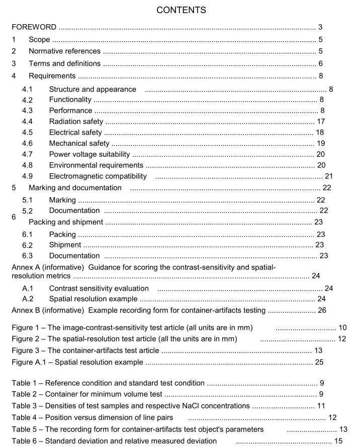
Except where otherwise specified,tests shall be carried out within the standard testconditions shown in the third column of Table 1.For tests performed outside the standard test
conditions,the values of temperature,pressure and relative humidity shall be stated and theappropriate corrections,if any,made to give the response under reference conditions. Alltests ‘in 4.3 shall be performed with the same values of these reference environmentalconditions. Reference conditions are given in the second column of Table 1.
The values in Table 1 are intended for tests performed in temperate climates. ln otherclimates,the actual values for the test shall be stated. Similarly atmospheric pressure lowerthan 70 kPa may be permitted at higher altitudes. lf the system is to be operate outside theenvironmental standard test conditions,testing shall be ‘performed at these non-standardconditions.
For the system under test,the imagequality test report shall include manufacturer,manufacture date,model No., serial No., software version,environmental conditions,serialNo. of the test articles, type and serial No. of X-ray emitter. For all performance requirements in 4.3,image evaluation shall be based on images acquired under normal security-screeningoperation mode including exposure time, high voltage, and any other adjustable parameters.
4.3.2Requirement on inspection time
4.3.2.1Requirements
The object inspection time shall not be more than 30 s. In single slice mode, if available,theinspection time shall be no more than 10 s.
4.3.2.2Test method
The system shall conduct an inspection for a test sample and the measurement/scanning timeand mode shall be recorded, and comply with the requirement of 4.3.2.1.
4.3.3 Requirement on minimum volume of liquid to be inspected4.3.3.1 Requirements
The system shall be able to inspect volumes of liquid that are 2 100 ml. The shape of thecontainer used to test for minimum scannable volume shall be a cylinder with a diameter of 50 mm.
4.3.3.2Test method
Fill the container TCO1,defined in Table 2, with water,and use the sample to performinspection.Such test shall be normally achieved and finally give an inspection result.
4.3.4 Image contrast sensitivity Requirements 4.3.4.1 The system’s image contrast sensitivity shall be sufficient to achieve discrimination between samples with physical density that differs by less than or equal to 3 % from that of water. The evaluation report format for this metric is given in Annex A, Table A.1.
4.3.4.2 Description of the image-contrast-sensitivity test article Using image contrast, this metric gauges effective liquid density resolution or sensitivity. The test article consists of 6 cylindrical cavities in a large cylindrical base, each filled with a different density liquid, as shown in Figure 1. The large cylinder is made of polyethylene. Each cavity is filled with distilled water or NaCl water solutions of different concentrations which is contained with a lid. Ensure the liquids are chemically stable over the period of testing. Relative densities of the liquids are given in Table 3.
