IEC 62499 pdf – Railway applications – Current collection systems – Pantographs, testing methods for carbon contact strips
IEC 62499 pdf – Railway applications – Current collection systems – Pantographs, testing methods for carbon contact strips
5.2.4.2.2 Test at specified temperature Test specimens shall be prepared in accordance with 5.2.4.2.1 . Specimens shall be cooled / heated to –40 °C, 1 00 °C, 200 °C, 250 °C and the steady state temperature recorded in test
5.2.1 whether it is greater or lower than 250 °C. The temperature shall be measured at the retention interface of the carbon and supporting structure. It shall be verified that the temperature of the monitoring point is representative of temperature at the interface and maintained during the test. The force of failure of each sample shall be recorded. The characteristics of Τ s with temperature shall be provided.
5.2.4.2.3 Thermal fatigue test The contact strip used in 5.2.1 shall be thermally cycled from room temperature to the maximum temperature achieved in 5.2.1 .2 for 1 00 cycles. The electrical resistance shall be measured before and after the test (see 5.2.7). The shear strength of the contact strip shall be measured at the conclusion of the test by taking samples from the heated region. Test acceptance criteria: It shall be demonstrated that the electrical resistance and method of attachment of carbon to the carrier have not deteriorated during the test.
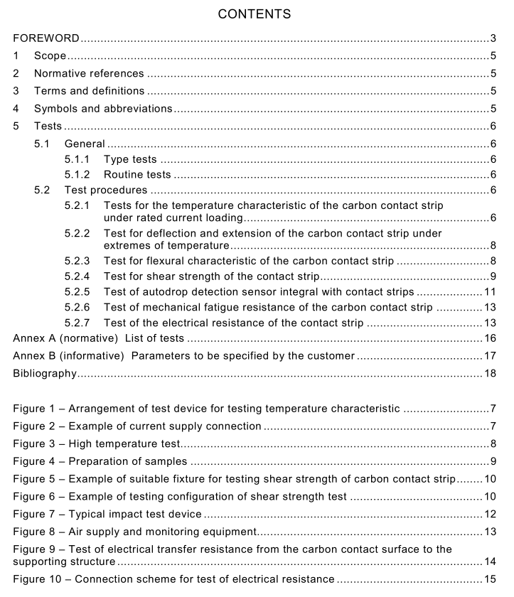
5.2.5 Test of autodrop detection sensor integral with contact strips
5.2.5.1 General The following tests shall demonstrate the sealing integrity of the contact strips, the flow continuity of the detection sensor and the operation of the detection sensor. NOTE The tests are applicable only to contact strips that are equipped with a channel at the base of the carbon as a sensing device.
5.2.5.2 Test method
5.2.5.2.1 Sealing integrity The carbon contact strip autodrop detection sensor shall be inflated for a minimum of 1 0 s at maximum operating pressure of the automatic dropping device (ADD). The maximum operating pressure shall be specified by the manufacturer and be agreed by the customer; a pressure of 1 0 bar is suggested. The air leakage rate shall be measured and demonstrated at room temperature. Maximum operating pressure shall be applied to the contact strip and the leakage rate shall be measured using a flow meter. Alternative methods of measurement are acceptable where it can be demonstrated that they equate to the above leakage rate at maximum operating pressure. Test acceptance criterion: The leakage rate shall not exceed 0,1 l/min.
5.2.5.2.2 Temperature test The carbon contact strip, tested under 5.2.2, where fitted with an autodrop detection sensor, shall be inflated during the test described in 5.2.2 to the maximum operating pressure of the automatic dropping device as specified by the manufacturer and be agreed by the customer (a pressure of 1 0 bar is suggested) and the sealing integrity during this test shall be continuously monitored. Test acceptance criterion: The leakage rate shall not exceed 0,1 l/min.
5.2.5.2.3 Flow continuity A flow meter shall be connected between the air supply and the contact strip. The supply shall be inflated to a minimum operating pressure of the autodrop system as specified by the manufacturer and be agreed by the customer (a pressure of 5 bar is suggested) and the blanking plug sealing the autodrop sensing system shall be removed.
Test acceptance criterion: The flow rate shall be recorded and shall exceed the minimum ADD requirement. NOTE See also 4.9 of IEC 60494-1 .
5.2.5.2.4 Impact function of the autodrop detection sensor
5.2.5.2.4.1 General The test shall demonstrate the operation of the autodrop detection sensor by impacting the contact strip and causing a severe failure of the carbon material.
5.2.5.2.4.2 Test method The carbon contact strip shall be supported at the interface between the pantograph and carbon carrier at a height to allow the striking point of the pin to be in line with the maximum wear line of the collector at mid span of the collector strip (example Figure 7). An air supply and monitoring equipment shall be connected and the system shall be inflated to the minimum operating pressure (Figure 8). The mass shall be retracted to a height h to provide sufficient energy to cause a successful operation of the autodrop detection sensor with one strike, or to an energy level as defined in the customer specification. In addition also a linear impact method producing the equivalent energy level defined by the customer is permissible. The energy shall be derived from the following formula: Energy (Joules) = Mass m (kg) × gravity g × height h (m)


